The blast furnace blower is the single piece of rotating equipment that cannot fail without stopping the furnace. Every cubic metre of air delivered to the tuyeres passes through it. A centrifugal turbo-blower running at 3,000–10,000 rpm under continuous load with compressed air outlet temperatures of 150–250°C gives maintenance teams very little margin between early warning and catastrophic failure — bearing vibration that reaches the trip limit of 160 microns can cross it in under one second, as documented in a published TRT failure analysis. The gap between a manageable repair and a furnace wind-break is not measured in days. It is measured in how many weeks of vibration trend data were available before the alarm fired — and whether anyone analysed them.
Blast Furnace Blower &
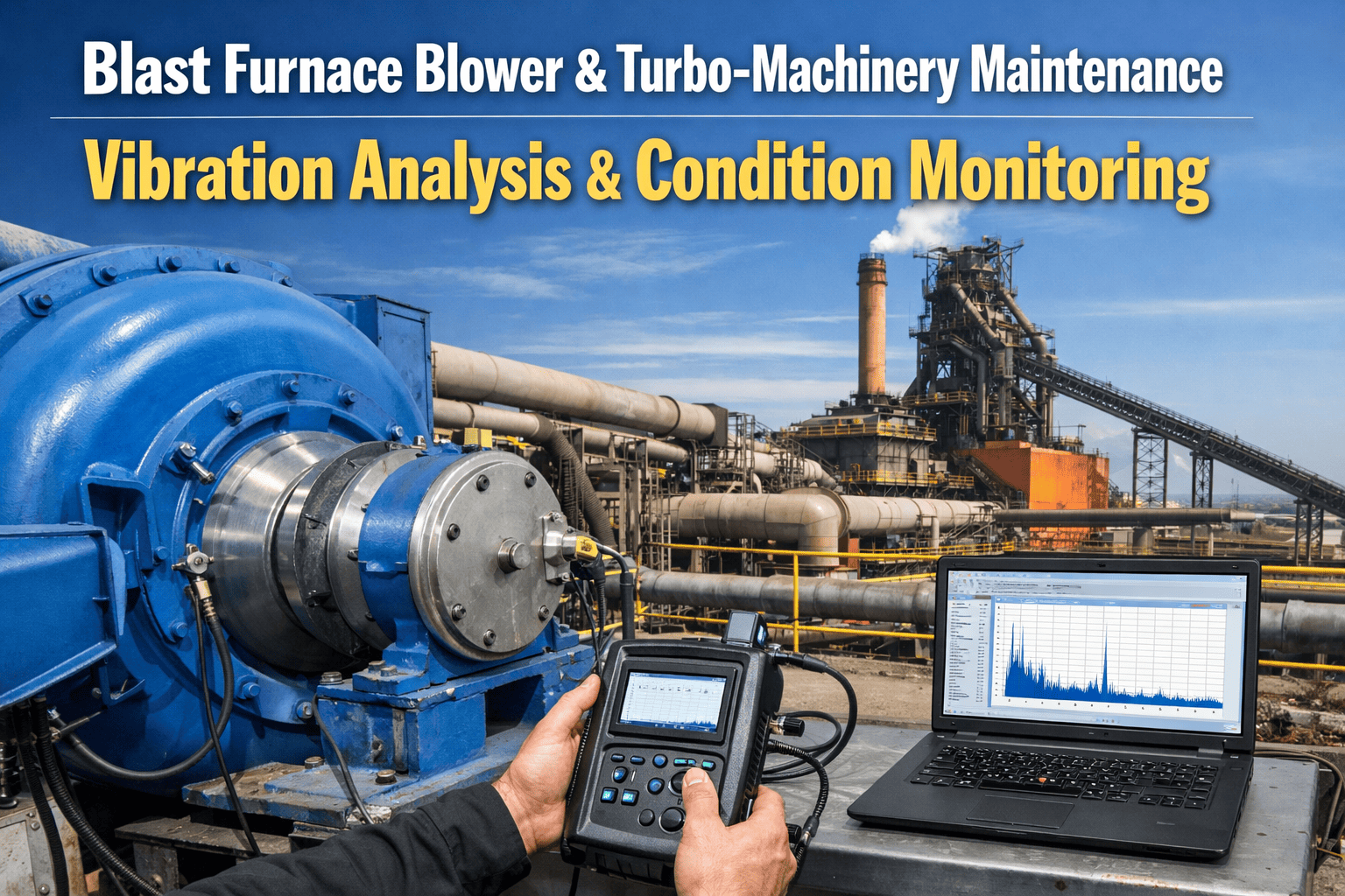
Turbo-Machinery Maintenance
Vibration Analysis · Surge Protection · Bearing Diagnostics · Oil Condition Monitoring · CMMS-Integrated Predictive Maintenance for Centrifugal and Axial BF Blowers
The BF Blower in the Air Blast System: What It Does and Why It Cannot Stop
Most blast furnaces are equipped with two centrifugal turbo-blowers with three or four compression stages — one operating, one on standby. Very large furnaces use axial compressors handling up to 1.5 million m³/hour at pressures up to 25 bar. The blower draws atmospheric air, compresses it to the blast pressure (typically 3–5 bar gauge for modern BFs), and delivers it to the cold blast main at 150–250°C from compression heat alone — before the hot stoves raise it to the final tuyere delivery temperature. Modern blast furnace blowers may be driven by steam turbines, electric motors with variable frequency drives, or — in BPRT (Blast furnace Power Recovery Turbine) configurations — partly driven by energy recovered from furnace top gas through a turbine on the same shaft.
A blower trip is an immediate furnace wind-break. The blast furnace must then be banked or blown down in a controlled sequence — a process requiring 34 sequential operations, with significant thermal shock to the furnace lining and production loss for every hour offline. Sign up for Oxmaint to begin trending your blower's vibration signatures and build the condition baseline that turns bearing alerts into scheduled repairs rather than emergency wind-breaks.
BF Blower Failure Modes: Mechanism, Signature, and Prevention
Vibration Signature Analysis: Reading What the Blower Is Telling You
Proximeter probes measure shaft-to-bearing gap to 1/100 mm precision on fluid-film bearings. Accelerometers on bearing caps measure frame vibration for rolling element bearings. Every component of a centrifugal blower — impeller, shaft, bearings, seals, coupling — produces a distinct vibration frequency relative to running speed. The key is correlating the frequency at which vibration amplitude increases with the component it identifies, enabling targeted diagnosis rather than reactive disassembly.
Digital twin research on axial blowers at blast furnace operations confirms that bearing shell vibration amplitude correlates strongly (r=0.79–0.84) with guide vane opening — meaning a simple fixed threshold of 90 μm cannot reliably distinguish operating condition variation from developing degradation without the operating condition context. Oxmaint's condition monitoring layer normalises vibration readings against guide vane position and operating pressure to eliminate false alarms while preserving genuine degradation detection. Book a demo to see condition-normalised vibration trending configured for your blower.
Unbalance or Eccentricity
Dominant vibration at running speed (1×N) in both radial directions. Phase is stable. Amplitude proportional to imbalance mass. Primary cause is impeller fouling from process dust accumulation — common in BF blowers handling gas with fines carryover. Monitor for gradual amplitude increase over weeks. Action: cleaning during next planned shutdown; balance check if amplitude exceeds 1× alarm limit.
Misalignment or Looseness
Elevated 2×N component — particularly in the axial direction — is the primary misalignment signature. Also appears with mechanical looseness. Cross-check with bearing temperature and coupling inspection. On steam-turbine driven blowers, 2×N elevation that develops over weeks after a startup typically indicates thermal growth misalignment rather than cold alignment error. Log every reading with operating temperature to enable thermal correlation.
Rolling Element Bearing Defects
Ball pass frequency outer race (BPFO) and inner race (BPFI) are calculable from bearing geometry and running speed. Early-stage defects appear as sidebands around these frequencies — amplitude increases by 3–6 dB are typically detectable 4–8 weeks before failure. Oil analysis showing increasing copper content confirms bearing cage material loss. Both signals together provide high confidence in bearing condition. Sign up for Oxmaint to configure defect frequency tracking for your blower bearings.
Surge Precursor / Oil Whirl
Vibration below running speed — typically 0.4–0.8×N — is the oil whirl signature in fluid-film bearings, which can progress to oil whip (sustained at 0.5×N) and rotor instability. Sub-synchronous vibration at 0.6–2.5 Hz indicates surge onset. Both signatures require immediate investigation: oil whirl from lubrication system issues, surge precursor from operating point approaching minimum flow limit. Both are detectable minutes to hours before trip-level vibration.
Aerodynamic Excitation and Impeller Issues
Blade pass frequency (number of impeller blades × running speed) should be monitored continuously. Elevated blade pass amplitude indicates aerodynamic instability — non-uniform flow distribution to the impeller from inlet guide vane issues or flow separation. Rising blade pass amplitude in an axial blower approaching the stonewall limit indicates flow velocity approaching sonic. This signature precedes blade damage in axial compressors.
Thrust Bearing Load and Surge Damage
Axial vibration at 1×N increases with thrust bearing degradation. During surge events, the rotor shifts axially, slamming against the thrust bearing at surge frequency (0.6–2.5 Hz). Post-surge inspection always requires axial clearance measurement on thrust bearing. Rising axial 1×N trend between surge events indicates cumulative thrust bearing damage from previous events — replace before the next surge event causes a trip. Book a demo to see axial vibration trending in Oxmaint.
Start Trending Blower Vibration Before the Next Alarm Fires
Oxmaint connects to your existing vibration sensors, normalises readings against operating conditions, and builds the degradation baseline that separates early warning from emergency response.
BF Blower Condition Monitoring: Parameters, Instruments, and CMMS Integration
| Parameter | Instrument | Alarm Threshold | Failure Mode Detected | CMMS Action |
|---|---|---|---|---|
| Radial vibration — shaft (X,Y) | Proximeter probes (fluid-film bearings) | Alarm: 80 μm · Trip: 160 μm | Bearing degradation, unbalance, misalignment, instability | Alert work order at alarm — trend from baseline |
| Bearing shell vibration (4 directions) | Accelerometers on bearing caps | Alarm: 90 μm — condition-normalised | Rolling element defects, resonance, structural looseness | Normalise against guide vane position before alarm |
| Axial vibration — thrust bearing | Axial proximeter or accelerometer | Rising trend above 1× baseline | Thrust bearing damage, surge events, misalignment | Post-surge inspection trigger — mandatory check |
| Bearing temperatures (RTD) | RTD sensors per bearing | Absolute limit per bearing type + 15°C/hr rise rate | Lubrication failure, overloading, bearing degradation | Temperature rise rate alert — independent of absolute |
| Discharge pressure and flow | Process transmitters | Operating point vs. compressor map limits | Surge approach, choke approach, operating margin loss | Real-time map monitoring — surge margin alert |
| Sub-synchronous vibration (0.4–0.8×N) | Proximeter with spectrum analyser | Any detectable sub-N amplitude from baseline | Oil whirl, surge precursor, rotor instability | Immediate investigation trigger — high risk signature |
| Lube oil pressure, temperature, flow | Pressure transmitters, RTD, flow meter | Pressure below minimum design · Temperature above limit | Lubrication failure precursor — pre-bearing failure | Oil system PM linked to bearing condition record |
| Oil analysis (wear metals, viscosity) | Laboratory spectroscopic analysis | Fe >50 ppm · Cu >20 ppm · Viscosity ±10% of spec | Bearing cage wear (Cu), journal wear (Fe), oil degradation | Quarterly PM work order — results logged per blower |
| Inlet guide vane position | Position transducer | Deviation from control setpoint | Surge margin — operating condition context for vibration | Logged with every vibration reading for normalisation |
| Dry gas seal differential pressure | Differential pressure transmitter | Below manufacturer minimum | Seal degradation from surge or contamination | Trending — post-surge mandatory inspection |
| Thresholds are starting points for Oxmaint configuration. Calibrate to your specific blower model, bearing type, and operating envelope. Fluid-film bearing vibration limits per API 670. Oil analysis limits per ISO 4406 cleanliness class and lubricant specification sheet. Manufacturer alarm and trip setpoints always take precedence. | ||||
How Oxmaint's Vibration Monitoring and Predictive AI Serve Blower Maintenance Teams
Condition-Normalised Vibration Trending
Vibration amplitude is logged against operating conditions — guide vane opening, discharge pressure, flow rate — at every reading cycle. Oxmaint's AI builds a condition-specific baseline per blower, eliminating the false alarms that cause maintenance teams to ignore the monitoring system. A 90 μm reading at 85% guide vane opening is normal; the same amplitude at 40% opening is anomalous. The system identifies which. Sign up free to configure condition-normalised trending for your blower fleet.
Frequency Spectrum Analysis and Defect Detection
Oxmaint's predictive AI analyses vibration frequency spectra from connected sensors — identifying BPFO, BPFI, BSF, and FTF defect frequency components as they rise above the noise floor weeks before overall amplitude crosses alarm thresholds. Sub-synchronous components (oil whirl, surge precursor) are flagged as high-priority alerts regardless of overall amplitude — because sub-N vibration signatures indicate instability conditions that escalate rapidly. Book a demo to see defect frequency tracking in Oxmaint.
Oil Analysis Records and Wear Metal Trending
Oil analysis results — iron, copper, aluminium, chromium particle counts; viscosity at 40°C and 100°C; water content; acid number — are logged per blower with date, sample point, and laboratory reference number. Wear metal trending compares each result against the blower's baseline and against alert thresholds (Fe >50 ppm, Cu >20 ppm) to identify which component is generating wear: iron from journals, copper from bearing cages, aluminium from seal faces. The quarterly oil analysis PM work order is generated automatically and linked to the bearing vibration record for correlated analysis.
Surge Event Documentation and Post-Surge Inspection
When anti-surge control actuates, Oxmaint logs the event with timestamp, operating conditions at onset, bypass valve response time, and post-surge vibration baseline shift. Each surge event generates a post-surge inspection work order for axial vibration baseline verification and dry gas seal differential pressure check — because cumulative surge damage to thrust bearings and seals is invisible until the next surge event triggers a trip. The surge event log provides the maintenance team with the forensic record needed to demonstrate whether an unplanned trip was the first event or the last of many. Start free to configure surge event logging for your blower system.
Bearing shell vibration amplitude correlates strongly with guide vane opening position — a simple fixed threshold of 90 μm is rarely successful in health status assessment without operating condition context. The analysis confirms that threshold-only monitoring will miss developing degradation and generate false alarms in equal measure. Condition-normalised trending is the only reliable approach for BF blower predictive maintenance.
Frequently Asked Questions
Connect Your Blower Vibration Data to a System That Actually Analyses It
Condition-normalised vibration trending, defect frequency monitoring, oil analysis records, surge event logging, and automatic PM scheduling — all in Oxmaint, connected to your existing blower instrumentation.