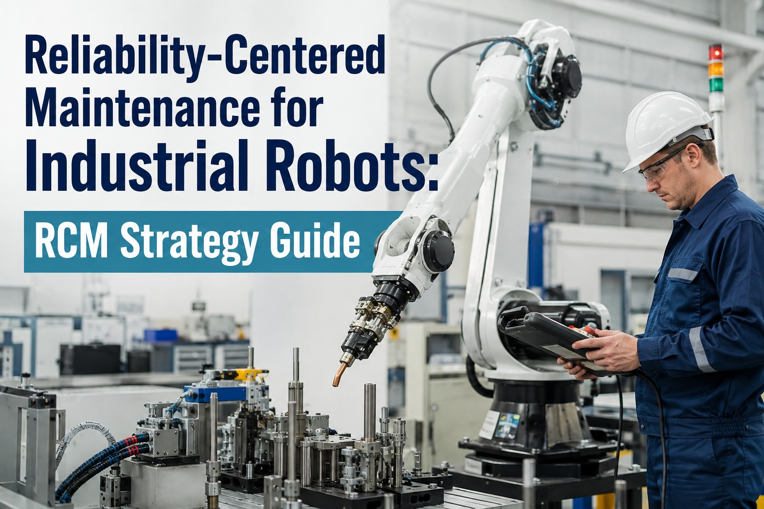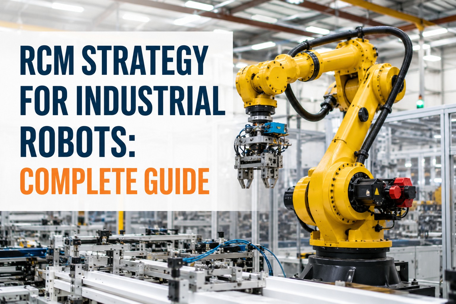
There are over 4.66 million industrial robots installed globally, according to the International Federation of Robotics — and a single articulated arm on an automotive body-in-white line executes 300,000+ weld cycles per year. Each robot contains dozens of critical components: harmonic and cycloidal reducers in every joint, servo motors with bearing races cycling under reversing loads, precision encoders drifting under thermal stress, and internal cable harnesses flexing millions of times inside the drag chain. When one robot cell stops unexpectedly, the ripple cascades through six or more downstream stations — and a single drifting joint can scrap painted bodies, damage weld tips, or crash tooling costing $100,000 or more. This is why industrial robots are the wrong asset class for calendar-based preventive maintenance. Nowlan-Heap Pattern F (infant-mortality-dominant) describes most robot subassemblies: fixed-interval overhaul actually introduces failures. What works is a proper Reliability-Centered Maintenance strategy — criticality analysis per robot cell, seven-question FMEA per axis, task selection driven by consequence, and PM intervals set to less than half the P-F interval that condition monitoring reveals. Bearing faults account for 40% of all servo motor failures, and encoder drift, harmonic drive fatigue, and cable-harness intermittent faults typically show 200 to 500 hours of P-detection lead time before functional failure — plenty of window to act. Below is the working RCM strategy for industrial robots, applied end-to-end. Start free and stand up RCM per-axis criticality on one robot cell this week, or book a demo to see the FMEA and condition-monitoring workflow mapped to your robot fleet.
Manufacturing · Robotics Reliability · SAE JA1011 · IFR · 2026
RCM Strategy for Industrial Robots: Complete Guide
The seven-question RCM framework applied to articulated-arm robots — criticality per cell, FMEA per axis, task selection by consequence, and condition-monitoring intervals derived from actual P-F data. Anchored to IFR global installation data, IEC 60068 environmental thresholds, and validated field results across automotive, aerospace, and general manufacturing.
-
4.66M
industrial robots installed globally (IFR World Robotics 2025)
-
300K
weld cycles per year on a single automotive body-line robot
-
200–500 hr
P-F detection lead time on most mechanical robot failure modes
-
$100K+
tooling damage from a single drifting joint that crashes the cell
The Asset Under Analysis
The Six Subassemblies That Actually Fail on a Robot
A meaningful RCM analysis starts with a clean asset breakdown. An articulated arm is not one asset — it is a stack of six coupled subassemblies, each with its own failure modes, P-F interval, and consequence profile. Skip this decomposition and every downstream RCM step is looser than it should be. Below is the working robot subassembly map with the primary failure mode and the detection signal for each.
Harmonic / Cycloidal Reducers
Primary failure: Flexspline wear, gear-tooth fatigue, grease breakdown leading to backlash and positioning error.
Detection: Motor current signature analysis, cycle-time drift, vibration kHz-band FFT.
Servo Motors
Primary failure: Bearing race spalling (40% of all servo failures), winding insulation degradation.
Detection: Vibration analysis, motor temperature trending, torque ripple monitoring.
Encoders
Primary failure: Optical/magnetic signal drift from thermal stress, electrical noise, contamination.
Detection: Position deviation trending, following-error alarms, torque ripple correlation.
Cable Harnesses (Dress Pack)
Primary failure: Internal wire fatigue from repeated flexing leading to intermittent comms and motor power loss.
Detection: Communication error logs, resistance drift on continuity check, cycle-count tracking.
Brakes & Holding Torque
Primary failure: Friction surface wear leading to sag on power cut, unsafe hold in E-stop.
Detection: Sag test, holding-torque measurement, quarterly safety verification.
Controller & Drive Electronics
Primary failure: IGBT thermal cycling, capacitor drift, power supply degradation.
Detection: Cabinet temperature trend, drive-fault log analysis, power quality monitoring.
The Seven Questions, Applied
The RCM Framework Walked Through on an Articulated Robot
SAE JA1011 defines the seven questions any compliant RCM analysis must answer. Below is the working walk-through applied to a representative six-axis welding robot on an automotive body line — showing what a real, defensible RCM strategy looks like at each step.
-
Q1
What are the functions and required performance standards?
Deliver TCP (tool centre point) to programmed weld locations with ±0.1mm repeatability, at rated payload, across a duty cycle of 300,000+ cycles per year. Secondary functions: safety hold on E-stop, thermal envelope compliance, controller uptime.
-
Q2
In what ways can it fail to deliver those functions?
Positioning-error failure, sudden stop, degraded cycle time, safety-brake hold failure, controller reset events, communication dropout. Typically 12–18 distinct failure modes per articulated arm across the six subassemblies.
-
Q3
What causes each functional failure?
Root causes mapped to subassembly: harmonic-drive backlash, servo bearing spalling, encoder drift, harness fatigue, brake wear, drive electronics degradation. Each cause carries its own consequence category and preferred detection signal.
-
Q4
What happens when the failure occurs?
Cell stop, downstream cascade across 6+ stations, potential tooling collision, painted-body scrap on paint lines, safety exposure on collaborative or high-speed cells. Consequence severity varies by cell criticality.
-
Q5
What are the consequences?
Categorised: safety (brake hold, high-speed cells), operational (line throughput), non-operational (quality drift), environmental (paint / chemical process). Criticality score assigned per cell reflecting downstream cascade depth.
-
Q6
What can be done to prevent or detect each failure?
On-condition tasks favoured — motor current signature, vibration FFT, position error trending — at intervals under half the observed P-F window (200–500 hrs on mechanical modes). Fixed-interval grease change and brake test kept for the small population that genuinely justifies calendar PM.
-
Q7
What if no proactive task is worth doing?
Failure-finding tasks scheduled on hidden functions — brake holding torque test quarterly, safety-scanner verification, E-stop circuit test. Run-to-failure accepted only on low-consequence, easily-swapped consumables (indicator lamps, non-critical sensors).
Failure Mode to Detection Method
The Working Matrix — What Signal Catches What Failure
The single most important operational output of a robot RCM analysis is the map from failure mode to detection method. High-frequency (kHz) sensor data catches early bearing and gear tooth defects; low-frequency (Hz) controller data catches drift and error patterns. Both matter, but for different failure modes. This is the working matrix.
| Failure Mode | Detection Signal | Data Source | P-F Interval (typical) |
|---|---|---|---|
| Harmonic-drive backlash | Motor current signature, cycle-time drift | Controller (Hz) | 300–500 hr |
| Cycloidal reducer wear | Vibration kHz FFT, torque ripple | External wireless sensor (kHz) | 200–400 hr |
| Servo bearing spalling | Vibration analysis, temperature trend | External sensor (kHz) + controller | 150–300 hr |
| Encoder drift | Position deviation, following-error alarm | Controller (Hz) | 100–250 hr |
| Cable harness fatigue | Comms error log, continuity resistance drift | Controller + cycle counter | Cycle-based |
| Grease breakdown | Torque signature, particle-count analysis | Controller + periodic sample | Interval-based |
| Brake holding-torque loss | Sag test, quarterly torque measurement | Failure-finding task | Hidden — test |
| Drive IGBT thermal drift | Cabinet temperature, drive-fault log | Controller + environmental sensor | 200–500 hr |
Where the OEE Gain Comes From
+18–28% Robot OEE Gain in Twelve Months — Broken Down by Lever
Manufacturing plants migrating from calendar-based robot maintenance to AI-native predictive RCM typically report a combined OEE gain of 18–28% within twelve months. The gain is not one thing — it is condition-based intervention on reducers, servo bearing prediction from vibration data, encoder drift caught before scrap, and controller anomaly detection. Oxmaint operationalises the full stack: FMEA per axis, condition-monitoring intervals derived from live P-F data, and mobile work orders dispatched to technicians with the right torque specs and PPE for each robot family.
Criticality Framework
Ranking Robot Cells — the Criticality Matrix
Not every robot cell deserves the same maintenance investment. RCM starts by ranking cells by consequence — cascade depth, safety exposure, replaceability, and cost-per-hour of the affected line. Below is the working criticality tier framework applied to industrial robotics.
Bottleneck Cells & Single-Point-of-Failure
Body-in-white welding, paint shop robots, aerospace drilling. Cell stop cascades through entire line. Full condition monitoring + AI predictive + failure-finding on all hidden functions. Zero calendar PM without RCM justification.
Redundant but High-Consequence Cells
Pick-and-place with hot-swap capability, secondary weld cells with buffer. Selective condition monitoring on reducers and servos; controller-data-only monitoring on encoders and drives.
Low-Impact Handling Cells
General material handling with adequate buffer, low-cycle inspection cells. Controller-data monitoring, failure-finding on safety functions, run-to-failure accepted on non-critical consumables.
Backup or Development Cells
R&D cells, backup units, low-utilisation robots. Basic PM on grease and brakes only; run-to-failure on the rest with sparing strategy. Maintenance dollar redeployed to Tier A.
Built for Robotics Reliability
How Oxmaint Runs the Robot RCM Programme End to End
-
Per-Axis FMEA
Failure Modes Tracked at Subassembly Level
Every robot in the asset register broken down to the six subassemblies. FMEA maintained per axis with live failure-mode tags — no more "robot down" tickets that hide the actual root cause.
-
Condition Data Ingest
Controller (Hz) + External Sensor (kHz)
Both data rates flow into the same asset record. Controller data via OPC-UA for position error, torque, and drive faults; external wireless vibration and temperature sensors for early-stage bearing and gear damage.
-
P-F Auto Scheduling
Inspection Cadence Under Half P-F
Inspection intervals set at less than half the documented P-F window per failure mode — 100 hrs for encoder drift, 150 hrs for servo bearings, 300 hrs for harmonic drives. Guaranteed catch before functional failure.
-
Cycle-Count Triggers
Cable Harness & Grease on Actual Duty
Cable-harness replacement and grease change scheduled against actual cycle count from the controller, not calendar time. High-duty cells serviced when they need it, low-duty cells not over-serviced.
-
Mobile Work Orders
Torque Specs, PPE, Photo History In-Hand
Technicians receive dispatched work orders on mobile with the correct torque specs per robot model, PPE requirements, and the last three service photos on that asset. Zero paper.
-
SAP / Maximo Overlay
Preserves Your Existing ERP
Overlay mode ingests robot asset hierarchy and work-order state from SAP PM or IBM Maximo. AI-generated work orders push back into your ERP for financial and stores integration.
Measured Outcomes
What Robot Reliability Programmes Report
-
+18–28%
Combined Robot OEE Gain in Year One
Manufacturing operations migrating from reactive robot maintenance to AI-native predictive RCM consistently report this range within 12 months across mechanical, servo, and controller failure categories.
-
200–500 hr
P-F Detection Lead Time
Joint bearing wear, servo encoder drift, and harmonic-drive fatigue are the most reliably detectable failure modes — with plenty of intervention window before functional failure.
-
$100K+
Single-Crash Loss Prevented
One caught encoder drift prevents one crashed cell, one scrapped body-in-white, or one damaged toolset. The ROI arithmetic on Tier A cells is unambiguous.
-
$0
Free Forever Plan to Start
Cloud-based, mobile-first. Stand up per-axis FMEA on one Tier A robot cell, prove the P-F workflow, and scale to fleet-wide when the reliability gain is validated.
Frequently Asked
Robot RCM Questions
Do we need external sensors, or is controller data enough?
Both are needed for the full picture. Controller data (sampled at Hz) is excellent for position error, motor current, torque ripple, and drive fault logs — enough to catch encoder drift, harmonic-drive backlash, and controller anomalies. External wireless vibration and temperature sensors (sampled at kHz) are required to catch early-stage bearing spalling and gear-tooth defects on reducers and servos. On Tier A cells you want both; on Tier C cells controller-data-only monitoring is usually sufficient. Book a demo to see the dual-data ingest workflow.
Do wireless sensors require modification to the robot's internal wiring?
No. Wireless vibration and temperature sensors mount externally on the joint housing, gearbox, or servo motor without any modification to the robot's internal wiring or controller. This preserves the manufacturer warranty and keeps the deployment reversible. Battery-powered sensors typically last 3–5 years on standard sampling rates.
How does this integrate with our robot OEM (Fanuc, ABB, KUKA, Yaskawa) controllers?
Oxmaint ingests robot controller data via standard OPC-UA endpoints, MTConnect, and vendor-specific APIs (Fanuc FOCAS, ABB Robot Web Services, KUKA OPC-UA, Yaskawa MotoLogix). Position error, motor current, torque, drive faults, and cycle counts flow into the FMEA in real time. No changes to the robot program or teach pendant required. Start free and connect your first robot controller today.
Is a full RCM workshop required before deployment?
No. Oxmaint seeds the initial FMEA per axis from robot-industry-standard failure-mode libraries, OEM service manuals, and your historical work-order data. Reliability engineers validate and refine — a matter of days, not the 6–18 months a traditional workshop-driven RCM takes per asset class.
Is there a free plan to prove this on one robot cell?
Yes. Oxmaint offers a free forever plan — enough to stand up per-axis FMEA on one Tier A robot cell, connect controller data, run condition-based scheduling, and prove the reliability gain. Cloud-based, mobile-first — no server procurement or infrastructure commitment to start. Sign up for the free plan and pilot on one robot cell today.
Six Subassemblies · Seven Questions · Four Tiers
Retire Calendar PM on Robots. Use the RCM Framework the Data Justifies.
Industrial robots are the wrong asset class for one-size-fits-all preventive maintenance. Nowlan-Heap Pattern F describes most robot subassemblies — calendar overhaul introduces failures. What works is the seven-question RCM framework, per-axis FMEA, criticality ranking by cell, and condition monitoring at less than half the P-F interval. Oxmaint operationalises the entire stack: FMEA per axis, dual controller and sensor data ingest, cycle-count triggers, and mobile work orders with the right torque specs per robot family.