A motor or pump bearing does not fail without warning — it fails without a listener. In the weeks before catastrophic collapse, every bearing broadcasts its deterioration through rising vibration amplitudes, shifting frequency signatures, and climbing surface temperatures. The problem is that most facilities have no infrastructure to receive that signal. Walk-around inspections sample assets for 30 seconds every few weeks; the bearing that begins spalling on day 3 of a 28-day cycle fails before the next technician arrives. Bearing failure is the single largest cause of motor and pump downtime, responsible for over 51% of all rotating equipment failures globally — yet it remains almost entirely preventable with continuous vibration monitoring paired with a CMMS that converts sensor thresholds into planned work orders. Start a free trial to see how Oxmaint maps bearing condition to automated maintenance scheduling, or book a demo and walk through your own rotating asset portfolio with one of our reliability specialists.
Motor & Pump Vibration Monitoring: Bearing Failure Detection Guide
How FFT spectrum analysis, bearing fault frequencies, and continuous RMS velocity trending detect inner race, outer race, ball, and cage defects 2–8 weeks before catastrophic failure — and how CMMS work orders close the loop automatically.
What Is Motor and Pump Vibration Monitoring?
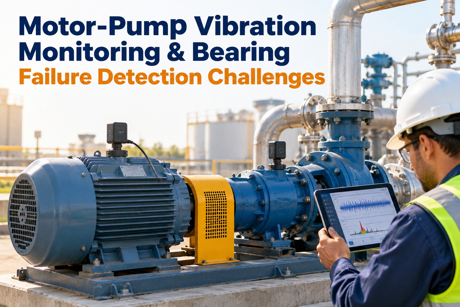
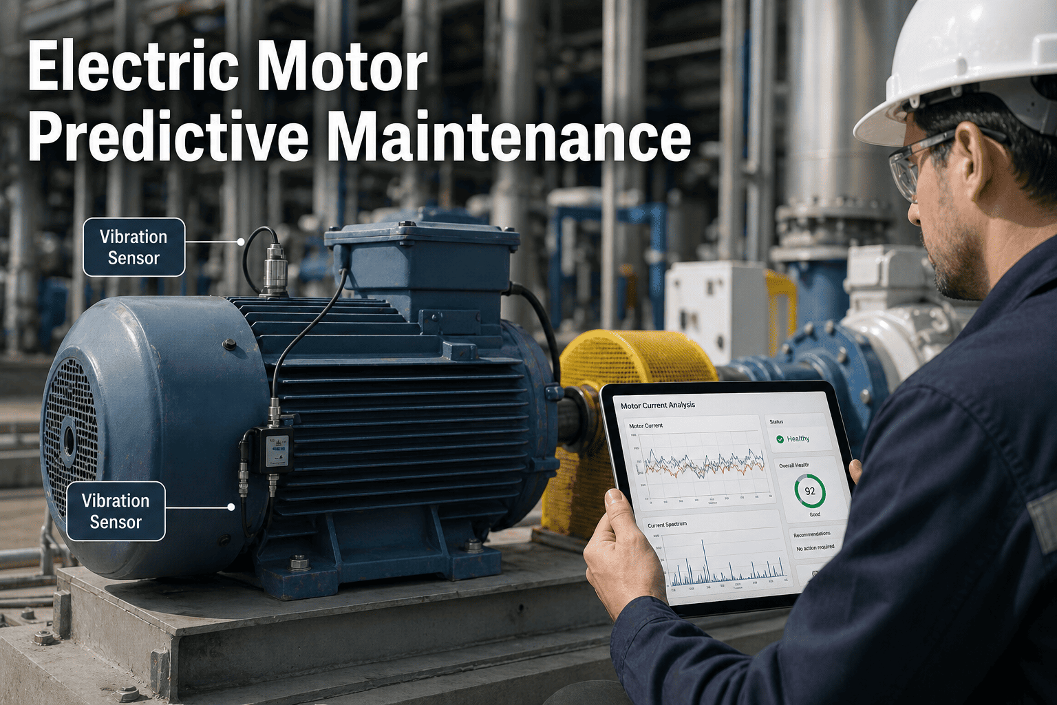
Motor and pump vibration monitoring is the continuous measurement of mechanical vibration at defined points on rotating assets — typically the drive-end and non-drive-end bearing housings — using accelerometers or velocity sensors. Readings are captured as RMS velocity (mm/s), peak acceleration (g), or both, and transmitted to a monitoring platform that compares real-time values against established baselines and defined alarm thresholds.
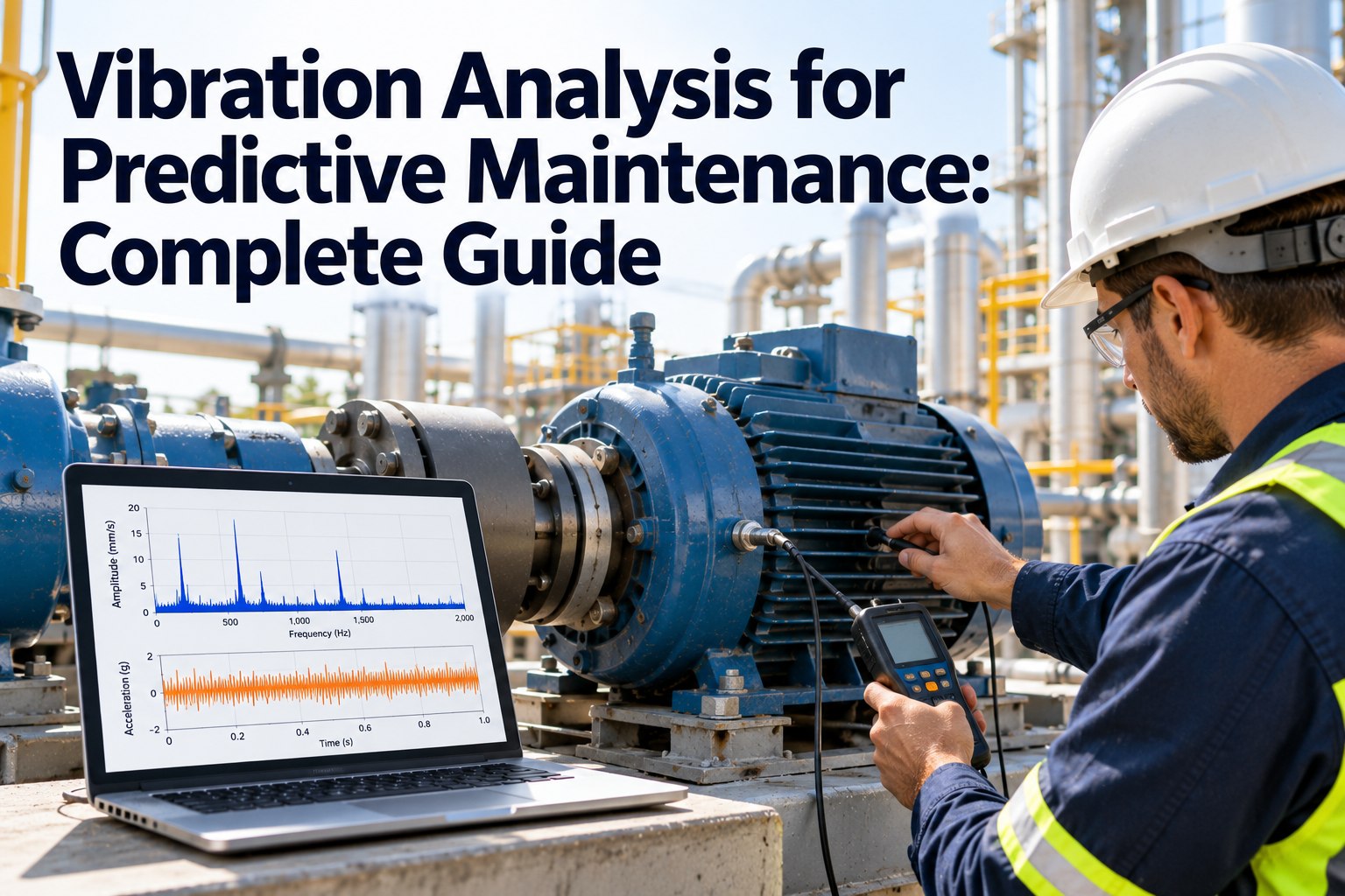
The physics is straightforward: a healthy bearing running at its design load produces a predictable vibration signature. As raceways, balls, or cages develop defects — from fatigue spalling, contamination, inadequate lubrication, or misalignment-induced overload — the vibration amplitude rises and new frequency components appear in the spectrum. FFT (Fast Fourier Transform) analysis decomposes the raw time-domain signal into its component frequencies, revealing exactly which bearing component is degrading and at what severity stage. Teams that deploy this methodology with CMMS integration consistently eliminate unplanned bearing failures within two maintenance cycles — start a free trial to connect your first motor or pump to Oxmaint, or book a demo to see bearing fault detection mapped to your asset hierarchy.
Six Reasons Bearing Detection Programs Fail Without a System
Finance committees understand capital risk — but maintenance teams lose credibility when bearing failures happen repeatedly despite "having sensors." These are the six patterns that destroy PdM program ROI before it starts.
Monthly walk-around checks leave a 672-hour window in which a bearing can begin degrading and reach catastrophic failure without any detection. Rapid-onset failures from contamination ingress complete their cycle in 48–96 hours — entirely invisible to periodic inspection programs.
A single vibration reading captured with a handheld analyzer means nothing without trend history. Without knowing where the asset started and which direction it is moving, 4.2 mm/s could represent normal operation or a rapidly deteriorating bearing three weeks from failure.
When a bearing fails without warning, it rarely fails alone. Bearing collapse at high RPM damages the shaft, destroys the housing, and in pump applications can wreck seals and impellers simultaneously. A planned $600 bearing replacement becomes a $20,000 shaft and housing rebuild.
Most sensor platforms send alerts to email inboxes checked irregularly. Without direct CMMS integration, every alert requires a human to manually create a work order — a step frequently delayed, missed, or completed only after the failure has already progressed beyond intervention range.
Replacing a bearing without identifying why it failed guarantees the same failure within 12–18 months. Misalignment-induced BPFI, overlubrication-caused BSF, and contamination-driven BPFO failures each require different corrective actions — only spectrum analysis reveals which applies.
Without condition trend data, there is no defensible basis for projecting which motors and pumps require capital replacement in years 2–5. Finance teams receive asset replacement requests with no supporting degradation data — leading to deferred replacements and the high-cost emergency failures that follow.
The Bearing Failure Detection Framework: 6 Technical Stages
A structured bearing monitoring program follows six sequential stages — from initial baseline collection through CapEx integration. Each stage builds on the previous one to create a continuously improving reliability program.
Sensors collect continuous RMS velocity and temperature readings for 30 days under normal operating conditions. This establishes an asset-specific statistical baseline — the unique vibration fingerprint of that motor or pump at its typical load and speed. Thresholds are set at 125% and 175% of the baseline, not generic industry values, because every asset behaves differently.
RMS velocity is trended over time against ISO 10816 severity zones A through D. Trend direction matters as much as absolute value: a reading of 3.8 mm/s rising 0.4 mm/s per week demands more urgency than one stable at 5.0 mm/s for six months. Both absolute threshold and rate-of-change rules are applied simultaneously.
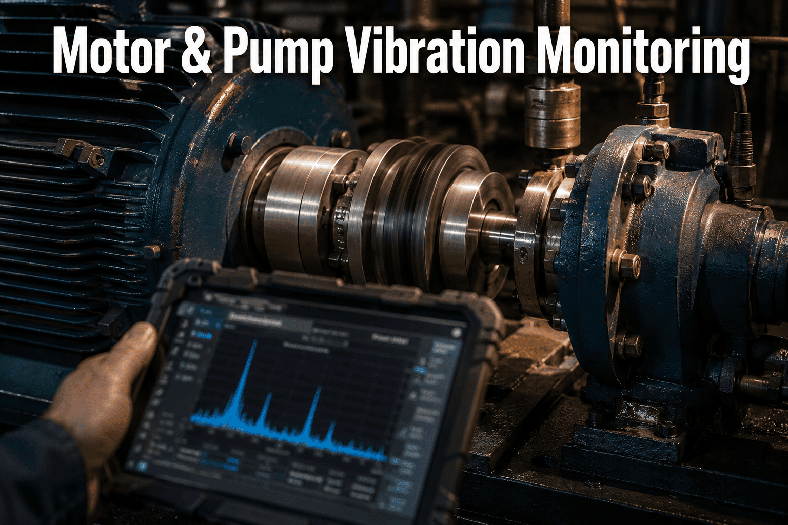
When overall levels rise above alert threshold, a detailed FFT spectrum is captured. The spectrum plots vibration amplitude against frequency (Hz), revealing individual peaks at bearing defect frequencies, gear mesh frequencies, shaft unbalance (1X running speed), and misalignment (2X running speed). Each peak type points to a different fault — enabling targeted repair, not blind replacement.
Each bearing has four characteristic fault frequencies: BPFO (outer race), BPFI (inner race), BSF (ball), and FTF (cage). A peak at BPFO indicates outer race spalling; BPFI points to inner race damage. This specificity allows parts to be sourced before the technician arrives on site — eliminating expedited procurement costs entirely.
Surface temperature at the bearing housing provides a secondary confirmation signal. A rising temperature delta — particularly one rising faster than ambient — confirms increased friction. In misalignment and lubrication-failure cases, temperature often rises before vibration amplitude increases significantly, providing an independent early warning on a different physical mechanism.
When the sensor threshold is crossed, Oxmaint generates a work order automatically: asset identified, fault type populated from the alarm type, priority level assigned based on severity zone, parts list pre-populated from the spare parts register, and the responsible technician notified. The detection-to-action gap collapses from days to under 60 seconds.
See Bearing Fault Detection on Your Own Assets
Oxmaint connects sensor data to automated work orders — so every threshold breach becomes a planned maintenance task, not a surprise breakdown. See measurable results in the first 30 days. No heavy implementation required.
Bearing Fault Frequencies — What Each Measures and How to Use It
Reliability engineers use four bearing fault frequencies to identify which component is degrading and what corrective action is required. Understanding each frequency type is the difference between targeted repair and costly guesswork that repeats the same failure.
| Fault Frequency | Bearing Component | Common Root Cause | ISO 10816 Alarm Onset | Corrective Action |
|---|---|---|---|---|
| BPFO — Ball Pass Frequency Outer Race | Outer raceway | Overloading, contamination ingress, static denting | Zone B–C boundary: 4.5–7.1 mm/s | Bearing replacement; inspect housing for contamination path |
| BPFI — Ball Pass Frequency Inner Race | Inner raceway | Shaft misalignment, bending loads, press-fit fretting | Zone B onset: rising trend above 2.8 mm/s | Replace bearing; perform laser alignment; inspect shaft for runout |
| BSF — Ball Spin Frequency | Rolling balls or rollers | Overlubrication, contamination, manufacturing defect | Often appears with temperature delta rise before vibration alarm | Relubricate correctly; replace bearing; audit lubrication procedures |
| FTF — Fundamental Train Frequency | Bearing cage | Lubricant starvation, high-speed operation, cage wear | Low amplitude — often precedes BPFO/BPFI by weeks | Immediate replacement; cage failure can scatter balls catastrophically |
| 1X Running Speed Peak | Shaft or rotor | Rotor unbalance, residue buildup, missing balance weight | Zone C: 7.1 mm/s — requires urgent correction | Dynamic balancing; inspect for buildup or erosion on rotating element |
How Oxmaint Closes Every Gap in Bearing Detection
Most facilities know they need better bearing oversight. The barrier is always the same — no single platform connects sensor data, maintenance history, work order automation, and CapEx forecasting. Oxmaint closes every gap in one integrated system.
Every motor and pump carries a live condition score (1–100) updated with each sensor reading. Reliability managers see an instant portfolio-wide health view — which assets are trending toward alarm, which are stable, and which require imminent intervention — without opening a single spreadsheet.
When a sensor reading crosses a configured threshold, Oxmaint auto-creates a work order: asset identified, fault type described, priority set, technician notified, and spare parts pre-populated from the asset's parts register. Detection-to-dispatch in under 60 seconds — no email chains, no manual entry.
Sensor-driven maintenance history automatically feeds MTBF, MTTR, availability %, and planned vs. unplanned maintenance ratio calculations. Operations directors see live OEE impact without manually cross-referencing sensor logs against CMMS histories or producing manual reports.
Condition score trend rates feed Oxmaint's CapEx engine, projecting asset replacement costs 5–10 years forward. Finance receives investor-grade CapEx reports backed by real degradation data — not age-based assumptions or gut estimates — starting from month 3 of live operation.
Walk-Around Inspection vs. Continuous Vibration Monitoring
The gap between periodic inspection and continuous sensor monitoring is not incremental — it is categorical. These are the operational differences that drive the ROI case for a structured PdM program backed by CMMS integration.
| Operational Dimension | Walk-Around Inspection | Continuous Wireless Monitoring + CMMS |
|---|---|---|
| Sampling Frequency | 30–60 seconds per asset, every 2–4 weeks | Every 1–60 minutes, 24/7, automatically |
| Failure Detection Window | Detected only on scheduled visit — often post-failure | 2–8 weeks advance warning via threshold trending |
| Root Cause Identification | No spectrum history — fault type unknown at inspection | BPFO, BPFI, BSF, FTF peaks identify specific fault component |
| Trend Data Available | Sparse snapshots — no statistical baseline possible | Continuous trend with baseline and rate-of-change tracking |
| Work Order Generation | Manual — technician records reading, creates WO separately | Automatic — threshold breach fires WO in under 60 seconds |
| Average Repair Cost | 4.8× higher — emergency labor, premium parts, cascade damage | Planned cost — stocked parts, scheduled crew, no secondary damage |
| CapEx Forecasting | No degradation data — capital requests unsupported by evidence | 5–10yr CapEx model driven by live condition score trends |
Motor and Pump Vibration Monitoring — Common Questions
The highest ROI assets are those with rotating components running continuously: electric motors above 5 kW, centrifugal and positive displacement pumps, HVAC and process fans, industrial gearboxes, and compressors. The common factor is a bearing or gear mesh that generates a detectable vibration signature as it degrades. Start a free trial to begin building your critical asset priority list in Oxmaint.
Bearing fault frequencies — BPFO, BPFI, BSF, and FTF — are calculated from the bearing's geometry (number of rolling elements, contact angle, pitch diameter) and the shaft's running speed in RPM. Most bearing manufacturers publish these values in their product datasheets. Oxmaint's asset registry stores bearing specifications and calculates expected fault frequency ranges per asset — book a demo to see how this maps to your specific bearing inventory.
The minimum is two accelerometers per asset: one on the drive-end bearing housing and one on the non-drive-end bearing housing. For pumps, a third measurement point on the pump casing bearing is recommended where accessible. Most wireless sensor implementations use a single triaxial sensor per bearing housing, giving six measurement readings per asset from two sensor nodes — full bearing coverage at minimal hardware cost.
Physical sensor installation on standard motors and pumps takes 15–30 minutes per asset. Baseline establishment takes 2–4 weeks of continuous data collection. First actionable alerts typically fire within 30–60 days. Full program ROI visibility — documented avoided failures and cost comparisons — is usually available within 90–180 days of going live. Sign up for Oxmaint to begin your deployment today.
Yes. For pharmaceutical, food, and beverage facilities, Oxmaint provides GMP-compliant audit trails: every sensor reading timestamped, every work order documented with technician sign-off, every replacement recorded with part number, batch, and installation date. The platform is structured for 21 CFR Part 11 and FSMA compliance without additional configuration — book a demo to see the compliance workflow applied to your facility type.
Stop Losing to Failures You Could Have Predicted
Connect your motors and pumps to continuous condition monitoring. Let Oxmaint convert threshold breaches into planned work orders, condition trends into CapEx forecasts, and sensor data into the reliability program your facility deserves — live in days, measurable results in 30.