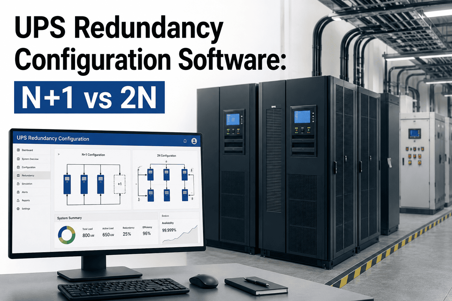
A single UPS failure inside a data center or hospital central plant can cascade into a facility-wide outage within seconds, which is why redundancy topology is one of the first decisions engineers lock down long before a single rack is powered on. N+1 configurations add one extra UPS module beyond the calculated load requirement, protecting against a single unit failure while keeping capital and footprint costs contained. 2N configurations mirror the entire UPS system end to end, so two fully independent power paths exist and either one alone can carry the full critical load if the other is lost. Facilities comparing 2N against 2(N+1) usually discover the harder problem isn't picking a topology on paper, it's proving during commissioning and every PM cycle afterward that failover behaves exactly the way the design intended. Teams that manage this with structured CMMS work order software, like the platform at OxMaint, can log every battery discharge test, transfer switch cycle, and load bank result against the exact redundancy path it protects, so the paper design and the operating reality never drift apart.
UPS Redundancy Configuration Software: N+1 vs 2N
How data center, hospital, and critical facility teams configure, test, and document N+1, 2N, and 2(N+1) UPS topologies with a CMMS built for uptime in 2026.
How Each UPS Redundancy Topology Actually Works
Choosing a topology on a single-line diagram is the easy part. The harder part is operating it correctly for years, since every added redundancy path also adds a transfer switch, a battery string, and a set of PM tasks that has to be tracked separately or the redundancy becomes theoretical rather than real. Facility teams that break this down system by system inside a CMMS avoid the common failure mode where a backup path exists on paper but was never actually tested under load.
- Shared UPS frame with one module beyond calculated load
- Single output bus, so a bus fault can still drop the load
- Lower capital cost per kW of protected capacity
- Common in edge sites and Tier II/III style deployments
- Battery strings sized per module, tested on rotation
- Two independent UPS systems, A path and B path
- Dual-corded IT load, each cord on a separate path
- Either path alone carries 100 percent of critical load
- Static transfer switches isolate faults per path
- Common in Tier IV and mission-critical hospital risers
- Two paths, each internally built as N+1
- Module maintenance on one path never removes redundancy
- Highest concurrent maintainability rating available
- Higher capital and floor space cost per protected kW
- Standard for hyperscale and top-tier colocation halls
OxMaint tags every UPS module, battery string, and transfer switch by which redundancy path it belongs to, so N+1, 2N, and 2(N+1) topologies stay documented, testable, and audit-ready instead of living only on a single-line diagram.
UPS Redundancy PM Schedule Facility Teams Run on OxMaint
Redundancy is only as strong as the last verified test, which is why every task below maps to a real UPS component and a documented test interval, not a generic annual walkthrough. Structuring preventive maintenance around the actual redundancy path is what lets a facility team answer an auditor's question with a timestamp instead of a guess.
| System | PM Task | Frequency | Reference Standard | OxMaint Automation |
|---|---|---|---|---|
| UPS Module | Output voltage and load-sharing check | Monthly | NETA MTS | Auto-generated PM with reading log |
| Battery String | Impedance and float voltage test | Quarterly | IEEE 450 | Trend alert on threshold drift |
| Battery String | Full discharge capacity test | Annual | IEEE 450 | Calendar PM with capacity log |
| Static Transfer Switch | Transfer time and load acceptance test | Semi-annual | NFPA 110 | Digital pass/fail checklist |
| UPS System | Load bank test at rated capacity | Monthly per path | TIA-942 | Path-tagged recurring work order |
| Redundancy Log | Path availability and failover documentation | Continuous, event-based | Facility SOP | Triggered work order on any failover event |
A 2N diagram only proves redundancy exists the day it is drawn. What actually protects the load six years later is whether every module on both paths has a documented, current test record, because the moment one path is quietly running degraded, you no longer have 2N, you have N with an expensive backup that nobody verified.
— Director of Critical Facilities, Tier IV Colocation Campus
Facilities that moved UPS redundancy tracking into a CMMS report catching path-level degradation weeks earlier than teams still relying on spreadsheets or vendor-only service reports, based on operator benchmarking across multi-site critical facility portfolios.
Frequently Asked Questions
OxMaint gives critical facility teams path-tagged PM scheduling, digital battery and load bank test records, transfer switch history, and one-click redundancy compliance exports, built for the pace of N+1, 2N, and 2(N+1) operations in 2026.