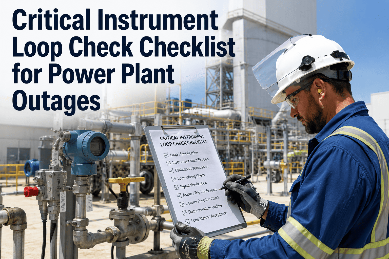
Instrument loop checks are the last line of defence between a mechanical completion and a safe plant startup. Every transmitter, every sensor, and every control signal must be verified end-to-end — from the field device through the junction box, to the marshalling panel, and into the DCS or SIS — before any process system is returned to service following an outage. A failed loop check discovered during commissioning is a recoverable problem. The same failure discovered after a plant is back online is a process safety event. Industry data shows that instrumentation failures account for 21 percent of unplanned power plant trips, a significant portion of which trace to loop check deficiencies left undetected during outage maintenance. OxMaint's Inspection Management module digitises loop check workflows with mobile field forms, calibration record storage, and automatic sign-off gating that prevents startup authorisation until every loop is confirmed closed. Book a demo to see instrument loop check workflows in OxMaint.
Checklist · Power Plant Instrumentation · Inspection Management · DCS / SIS Verification
Critical Instrument Loop Check Checklist for Power Plant Outages
Cold loop verification, hot loop signal testing, SIS functional testing, calibration record confirmation, and DCS response validation — the complete loop check framework for power plant outage recommissioning.
21%
Of unplanned power plant trips attributed to instrumentation failures — many preventable with rigorous loop check protocols
0 / 25 / 50 / 75 / 100%
Five test points required for each transmitter loop per standard commissioning practice
2 Teams
Required simultaneously — one field technician and one control room operator — with radio communication maintained throughout
4-20 mA
Standard signal range verified at every point — wire break detection at 3.5 mA, zero at 4 mA, full scale at 20 mA
Cold Loop vs Hot Loop — Understanding the Two-Phase Approach
Cold Loop Check
Performed with the system de-energised. Verifies wiring continuity, cable labelling accuracy, terminal connections, instrument tag verification, and correct I/O channel mapping at the DCS/PLC. No process fluid or power involved.
Cable continuity test — field to control room
Megger insulation resistance test on signal cables
Tag verification at instrument, JB, and DCS
Terminal torque and correct polarity confirmation
Loop drawing vs as-installed comparison
Hot Loop Check
Performed with the system powered. Verifies signal integrity across the full 4-20 mA range, DCS scaling and alarm setpoints, SIS trip function activation, and actuator response to controller commands.
Signal injection at 0%, 25%, 50%, 75%, 100%
DCS reading verified against injected value
Alarm and trip setpoint activation confirmed
Control output to actuator verified at 0% and 100%
HART diagnostic readback from smart instruments
Phase 01
Pre-Check Documentation and Preparation
Every loop check begins with documentation, not with tools. The loop folder must contain the current revision of the loop drawing, the P&ID showing the instrument tag, the instrument calibration data sheet from the most recent bench calibration, and the DCS configuration printout showing the I/O channel, engineering units, and alarm setpoints. Any discrepancy between the loop drawing and the as-installed configuration must be resolved through a formal redline or engineering change before the loop check proceeds — not corrected in the field without documentation.
Pre-Check Documentation Checklist
Before Any Field Activity
Loop drawing confirmed at current revision — drawing number, revision, and issue date recorded on loop check cover sheet; any pending engineering change affecting this loop confirmed as either incorporated or deferred with technical basis; marked-up (redline) drawings not acceptable as loop check basis without engineering sign-off
Record: Loop drawing rev on cover sheet · Role: Instrument Technician + Engineer
Instrument calibration records confirmed current — calibration data sheet for each instrument in the loop retrieved; calibration performed post-installation or post-bench-servicing; as-found and as-left values recorded; any instrument requiring recalibration before loop check actioned before proceeding
Record: Calibration data sheet attached to loop folder · Role: Instrument Technician
DCS/SIS configuration sheet printed and verified — engineering unit, zero and span values, alarm and trip setpoints, and fail-safe direction confirmed against approved instrument specification; HART device configuration sheet for smart instruments confirms device tag, PV range, and damping setting matches approved design
Record: DCS configuration printout in loop folder · Role: Control Systems Engineer
Test equipment calibrated and verified — HART communicator, current loop tester (4-20 mA source), calibrated digital voltmeter, and handheld communicator confirmed with valid calibration certificates; calibration due dates checked against loop check schedule; expired calibration on test equipment stops the loop check
Record: Test equipment calibration cert numbers on cover sheet · Role: Instrument Technician
Radio communication confirmed between field and control room — both field technician and control room operator confirm two-way communication before starting; communication channel designated and confirmed clear; loop check requires continuous communication — any loss of communication pauses the check until contact is re-established
Record: Communication check confirmed on cover sheet · Role: Both Technicians
Phase 02
Cold Loop Check — Wiring, Continuity, and Tag Verification
Cold loop checks are performed with the system de-energised and the instrument isolated from the process. The objective is to confirm that the physical wiring matches the engineering drawings exactly — every cable pair terminated at the correct terminal, labelled with the correct tag, and routed through the correct junction box. Cable labelling errors are the most common cause of loop check failures and, if undetected, lead to crossed signal paths that can cause false alarms, missed trips, or incorrect controller response.
Cold Loop Check Checklist
System De-Energised
Cable continuity verified from field instrument to DCS I/O card — continuity tester applied at field instrument terminals; control room operator confirms continuity indication at DCS terminal; both ends of every pair verified; any break or high-resistance joint located and repaired before proceeding to hot check
Record: Continuity pass/fail per cable pair · Role: Field Tech + Control Room
Insulation resistance test on all signal cables — megger test at 500V DC between each conductor pair and earth; minimum acceptable insulation resistance 10 MΩ for new cable, 1 MΩ for existing cable; any cable below 1 MΩ requires investigation before energisation; readings documented with megger serial number and test voltage
Record: Megger readings (MΩ) per cable ID · Role: Instrument Technician
Tag ferruling verified at instrument, junction box, marshalling panel, and DCS rack — field instrument tag matches loop drawing; junction box terminal label matches cable schedule; marshalling panel row matches channel assignment; DCS I/O channel tag confirmed on system faceplate by control room operator; any mismatch requires field correction before proceeding
Record: Tag verification sign-off at each node · Role: Field Tech + Control Room
Wire break detection verified — with instrument terminals disconnected, set current source to 3.5 mA and confirm DCS shows correct wire-break fault indication; wire break action (typically freeze, high or low alarm, or defined value) confirmed against approved configuration; incorrect fault response requires DCS configuration correction before startup authorisation
Record: Wire break fault indication result on loop check form · Role: Control Room Operator
OxMaint's mobile loop check forms let field technicians enter readings in real time while the control room operator signs off each test point digitally. Every loop check result, every calibration reference, and every sign-off is automatically linked to the work order and asset record — ready for audit export in minutes.
Phase 03
Hot Loop Check — Signal, Alarm, and Actuator Verification
Hot loop checks confirm that a live signal from the field instrument produces the correct reading, alarm, and control response at every point in the loop. The standard five-point test (0%, 25%, 50%, 75%, 100% of range) is the minimum required. For Safety Instrumented System inputs, additional testing at the trip setpoint in both the trip direction and the reset direction is mandatory — confirming not just that the trip fires at the correct value but that it resets correctly and does not exhibit hysteresis outside the design tolerance.
Hot Loop Check Checklist
System Energised — Field and Control Room Required
Five-point signal injection test completed — 4 mA (0%), 8 mA (25%), 12 mA (50%), 16 mA (75%), and 20 mA (100%) injected in sequence using calibrated current source; DCS reading at each point recorded by control room operator; acceptable tolerance within 0.5% of span or as specified in instrument data sheet; out-of-tolerance readings trigger field instrument recalibration before loop check can pass
Record: All five-point readings (injected vs DCS indication) on loop check form · Role: Field Tech + Control Room
Alarm setpoints activated and verified — low alarm and high alarm setpoints approached from below and above respectively; alarm activation confirmed on DCS faceplate with correct alarm message and priority; control room operator confirms alarm reaches plant alarm management system with correct identification; setpoint tolerance verified against approved instrument data sheet
Record: Alarm activation confirmation with setpoint values · Role: Control Room Operator
SIS trip function verified for safety-critical loops — trip setpoint approached in the trip direction; SIS logic solver confirms trip output activated; output to final element (solenoid valve, motor trip relay) confirmed at the actuator; reset from trip state verified by returning signal above the reset setpoint; both trip and reset values recorded and compared to approved Safety Requirements Specification
Record: SIS trip value, reset value, final element response · Role: Safety System Engineer
Control output verified to final control element — for control loops with an output to a valve positioner or motor drive: output stepped from 0% to 100% and 100% to 0%; valve or damper position at field verified at both limits and at 50%; hysteresis measured and confirmed within design tolerance; any valve stiction or positioner calibration issue resolved and re-tested before loop close
Record: Valve position readings at 0%, 50%, 100% output · Role: Field Tech + Control Room
Phase 04
Loop Close-Out and Startup Sign-Off
A loop is not closed until every test point has a recorded result, every discrepancy has been resolved and re-tested, and both the field technician and the responsible engineer have signed the cover sheet. In plants operating under formal Management of Change procedures, the loop close-out also requires confirmation that the as-tested configuration matches the approved design. Any loop that was modified during the check — recalibrated, rewired, or reconfigured — must have those changes captured in a formal modification record before the loop check close-out is signed.
Loop Close-Out Checklist
Required Before Startup Authorisation
All test points recorded with pass status — no outstanding FAIL items on loop check form; any item that failed and was corrected must have a second test result recorded confirming pass after correction; loops with unresolved failures must not be included in startup authorisation; outstanding loops listed on a punch list with responsible person and resolution target date
Record: Completed loop check form with all test results · Role: Instrument Technician
As-left configuration documented and matches approved design — any recalibration performed during loop check has as-left values recorded; any wiring corrections recorded with before-and-after description; DCS configuration changes made during check documented on a formal change request; no undocumented modifications acceptable at loop close-out
Record: As-left calibration data and modification records · Role: Instrument Engineer
Loop check sign-off by field technician and responsible engineer — both signatures required on loop check cover sheet; signed cover sheet uploaded to OxMaint against asset record and work order; loop check completion status updated in OxMaint to CLOSED; loop count reconciled against outage instrument loop check schedule before startup authorisation is processed
Record: Dual-signed cover sheet in OxMaint · Role: Technician + Instrument Engineer
Loop Check Efficiency — OxMaint vs Paper-Based Tracking
Paper-Based
4.2 hrs
Average time to locate a specific loop check record during a startup punch list review
vs
OxMaint Digital
Under 2 min
Instant search by loop number, tag, or asset — record retrieved with full test data and signatures
Paper-Based
23%
Of loop check forms found incomplete or missing signatures during startup audits
vs
OxMaint Digital
0%
Mandatory sign-off gates prevent loop from being marked closed with missing data
Paper-Based
8 days
Typical time to compile full loop check completion report for startup authorisation
vs
OxMaint Digital
Real-time
Live dashboard shows total loops, completed, open, and punch list items at any moment
Frequently Asked Questions
What is the difference between a loop check and a functional test?
A loop check verifies signal integrity and wiring from field instrument to control system. A functional test verifies that the complete system — including field instrument, signal path, logic controller, and final control element — performs its intended function under simulated or actual process conditions. Both are required before startup: loop checks precede functional tests.
OxMaint manages both as separate work order types with distinct completion gates.
Can a loop check be performed without isolating the instrument from the process?
How does OxMaint track outstanding punch list items from loop checks during an outage?
OxMaint automatically flags any loop with a FAIL result or an unresolved discrepancy as a punch list item, assigns it to the responsible technician or engineer, and tracks it through to close-out. The startup authorisation workflow in OxMaint cannot be completed while open punch list items remain on safety-critical loops, preventing inadvertent startup with unresolved instrumentation issues.
What standards govern instrument loop check requirements for power plants?
Key standards include ISA-5.1 for instrument symbols and identification, ISA-84 for Safety Instrumented Systems, IEC 61511 for SIS functional safety, and plant-specific commissioning procedures aligned with OEM requirements. For nuclear plants, 10 CFR 50 Appendix B governs QA documentation requirements for instrumentation on safety-related systems.
Explore OxMaint's compliance tracking features.
OXMAINT INSPECTION MANAGEMENT · POWER PLANT INSTRUMENTATION
Every Loop. Every Test Point. Every Sign-Off. One Audit Trail.
OxMaint digitises your entire instrument loop check process — mobile field forms, five-point test data entry, SIS trip confirmation, automatic punch list tracking, and instant export of completion records for startup authorisation and regulatory inspections.