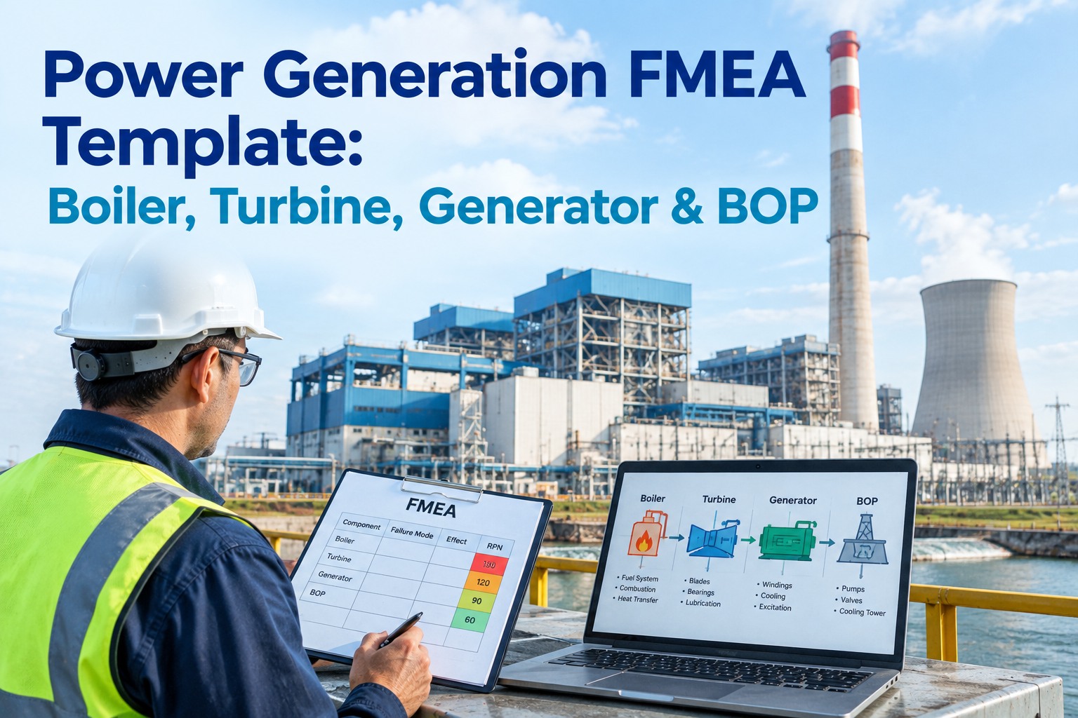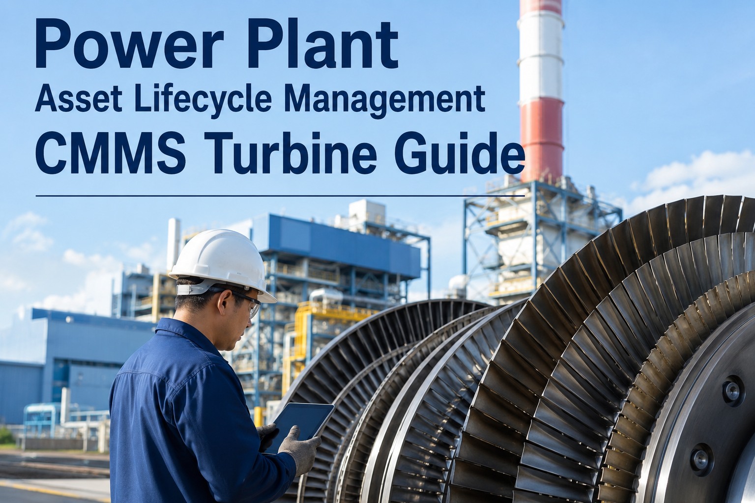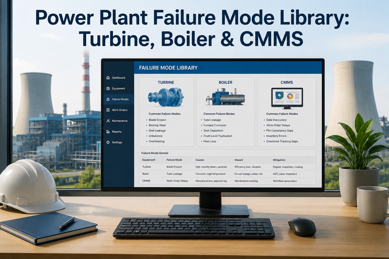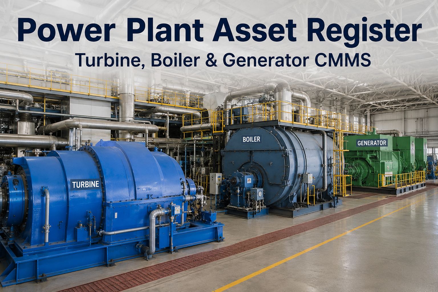
Building a power plant asset register that stops at "Gas Turbine Unit 1" or "Boiler 2" hides the very components that actually drive your maintenance — combustion cans, HP rotor stages, HRSG tube banks, generator windings. This guide walks reliability and maintenance managers through structuring a CMMS asset hierarchy down to the sub-component level, with concrete examples for gas turbines, steam turbines, HRSGs, and generators you can copy directly. Start a free OxMaint trial to build your hierarchy today, or book a demo and we'll walk you through a generation-specific setup.
Power Plant Asset Register: Turbine, Boiler & Generator CMMS
A field-tested asset hierarchy structure for generation plants — going below the unit level into the sub-components where PM scheduling, failure history, and spare parts tracking actually happen.
Why a flat asset list fails in power generation
Most plants inherit an asset register that lists major equipment — "GT-01," "ST-02," "HRSG-A," "GEN-01" — and stops there. When every work order, failure code, and spare part rolls up to a single parent record, you lose the ability to plan maintenance at the component level where it actually matters.
"GT-01 Combustion Inspection" logged against the parent turbine asset. No record of which of 14 combustion cans was pulled, which transition piece failed, or which first-stage nozzle segment was replaced.
- Fired hours tracked at unit level only
- Spare parts issued to a generic turbine code
- Failure history cannot isolate a recurring can or bearing
- OEM interval compliance is unverifiable at audit
"GT-01 → Combustion System → Combustion Can #07" carries its own fired-hour counter, its own PM schedule, its own failure history, and its own BOM — so the next CI pulls exactly the right parts and records.
- Component-level fired-hour and cycle tracking
- Spare parts linked to specific sub-assets
- Failure history isolates repeat offenders by serial number
- NERC/API/OEM intervals auditable per component
The three-level hierarchy every plant should use
A generation asset register works when each level answers a different question. The unit level answers "what's running?" The system level answers "what function does it perform?" The component level answers "what do we maintain, inspect, and track?"
Unit
The top-level generating asset — e.g., GT-01, ST-02, HRSG-A, GEN-01. Carries unit-level operating data: total fired hours, starts, capacity factor, unit availability.
System
Functional grouping within the unit — Combustion System, Hot Gas Path, Rotor & Blading, Feedwater System, Steam Path, Electrical & Winding. Defines the maintenance discipline and inspection scope.
Component
The maintainable item — Combustion Can #07, HP Stage 1 Rotor Blade Row, HP Evaporator Tube Bank, Stator Winding. Carries its own PM schedule, fired-hour counter, failure history, and BOM.
GT01-COMB-CAN07 so every component is uniquely identifiable, sortable, and readable in a work order without opening the hierarchy tree.
Gas turbine sub-component register
A gas turbine asset register needs to break the unit into the sub-components that drive combustion inspections (CI), hot-gas-path inspections (HGPI), and major inspections (MI). Below is a reference structure for an F-class heavy-duty gas turbine — adapt the can count and stage naming to your OEM frame.
| L1 Unit | L2 System | L3 Component | Tracking basis | Typical interval |
|---|---|---|---|---|
| GT-01 | Combustion System | Combustion Can #01–14 | Fired hours + starts | CI: 8,000 fh |
| GT-01 | Combustion System | Transition Piece #01–14 | Fired hours | CI: 8,000 fh |
| GT-01 | Combustion System | Fuel Nozzle Assembly #01–14 | Fired hours | CI: 8,000 fh |
| GT-01 | Hot Gas Path | Stage 1 Nozzle Segments | Fired hours + starts | HGPI: 24,000 fh |
| GT-01 | Hot Gas Path | Stage 1 Bucket Row | Fired hours + starts | HGPI: 24,000 fh |
| GT-01 | Hot Gas Path | Stage 2 Nozzle & Buckets | Fired hours | HGPI: 24,000 fh |
| GT-01 | Rotor & Bearings | #1 Bearing (Compressor End) | Vibration trend + hours | MI: 48,000 fh |
| GT-01 | Rotor & Bearings | #2 Bearing (Turbine End) | Vibration trend + hours | MI: 48,000 fh |
| GT-01 | Rotor & Bearings | Compressor Rotor | Starts + hours | MI: 48,000 fh |
| GT-01 | Air Inlet | Inlet Filter Stage (coarse + fine) | Pressure drop ΔP | Condition-based |
Steam turbine stages & rotor/blade tracking
Steam turbine maintenance is driven by blade integrity, rotor stress, and casing distortion. The asset register must track individual stage rows and rotor assemblies so that boresonic inspections, NDE blade checks, and casing metrology are recorded against the right component — not the unit.
| L1 Unit | L2 System | L3 Component | Inspection type | Typical interval |
|---|---|---|---|---|
| ST-02 | HP Section | HP Rotor (incl. blade rows 1–8) | Boresonic + NDE | Major: 10 yr / 100k fh |
| ST-02 | HP Section | HP Stage 1 Blade Row | Blade tip timing + NDE | Major: 10 yr |
| ST-02 | HP Section | HP Inner Casing | Casing metrology / distortion | Major: 10 yr |
| ST-02 | IP Section | IP Rotor | Boresonic + NDE | Major: 10 yr / 100k fh |
| ST-02 | IP Section | IP Blade Rows | NDE / blade root inspection | Major: 10 yr |
| ST-02 | LP Section | LP Rotor (last-stage blades) | Boresonic + L-0/L-1 NDE | Major: 10 yr / 100k fh |
| ST-02 | LP Section | LP Last-Stage Blade Row | Stress corrosion / NDE | Major: 6–10 yr |
| ST-02 | Bearings & Seals | #1–#4 Journal Bearings | Babbitt inspection + alignment | Major: 4–6 yr |
| ST-02 | Bearings & Seals | Thrust Bearing | Babbitt + pad inspection | Major: 4–6 yr |
| ST-02 | Steam Path | HP Nozzle Block / Diaphragms | Erosion / deposit mapping | Major: 10 yr |
HRSG tube banks & inspection tracking
The HRSG is where many plants lose register discipline — because a "boiler" is actually a stack of independent tube banks, each with its own degradation mechanism, inspection interval, and tube-replacement history. Register each bank as a separate L3 component so that tubing thickness data, tube plug records, and NDE results attach to the right surface.
| L1 Unit | L2 System | L3 Component | Primary degradation | Inspection basis |
|---|---|---|---|---|
| HRSG-A | HP Circuit | HP Economizer Tube Bank | Flow-accelerated corrosion | UT thickness / NDE |
| HRSG-A | HP Circuit | HP Evaporator Tube Bank | Caustic gouging / under-deposit | UT thickness / NDE |
| HRSG-A | HP Circuit | HP Superheater Tube Bank | Creep / oxidation | UT + replication |
| HRSG-A | IP Circuit | IP Evaporator Tube Bank | FAC / corrosion fatigue | UT thickness |
| HRSG-A | IP Circuit | IP Superheater Tube Bank | Creep | UT + replication |
| HRSG-A | LP Circuit | LP Evaporator Tube Bank | FAC | UT thickness |
| HRSG-A | Condensate | Condensate Preheater | Oxygen pitting / FAC | UT thickness |
| HRSG-A | Headers & Manifolds | HP Header (main steam) | Creep / ligament cracking | Replication + UT |
| HRSG-A | Casing & Duct | Inlet Duct / Transition | Thermal fatigue | Visual + NDE |
Generator windings & electrical sub-assets
Generator maintenance hinges on winding insulation health, stator core tightness, and hydrogen/cooling system integrity. The register should separate stator winding, rotor winding, and core as distinct L3 components — each with its own electrical test history (Megger, polarization index, EL CID, TEF) and its own rewind/replacement record.
| L1 Unit | L2 System | L3 Component | Key tests / tracking | Typical interval |
|---|---|---|---|---|
| GEN-01 | Stator | Stator Winding (main bars) | Megger, PI, partial discharge | Annual / major: 8–12 yr |
| GEN-01 | Stator | Stator Core | EL CID, knife test | Major: 8–12 yr |
| GEN-01 | Stator | Stator Winding Support / Side Ripple | Visual + tap tightness | Major: 8–12 yr |
| GEN-01 | Rotor | Rotor Winding | Megger, PI, RSO | Major: 8–12 yr |
| GEN-01 | Rotor | Rotor Body / Forging | Boresonic (if applicable) | Major: 10–15 yr |
| GEN-01 | Rotor | Retaining Rings | NDE / fluorescent penetrant | Major: 8–12 yr |
| GEN-01 | Cooling | Hydrogen Cooler (coils) | Leak test / cleaning | Annual |
| GEN-01 | Cooling | Seal Oil System | Oil quality / seal condition | Quarterly / annual |
| GEN-01 | Excitation | Exciter / Brushless Exciter | Insulation resistance | Annual |
| GEN-01 | Bearings | Generator Journal Bearings | Babbitt + alignment | Major: 4–6 yr |
How OxMaint structures your asset hierarchy
OxMaint CMMS is built around the unit → system → component model, so every work order, PM trigger, failure record, and spare part attaches to the right sub-component — not a generic parent.
Unlimited hierarchy depth
Build Unit → System → Component → Sub-component without hitting a flat-list ceiling. Each node carries its own attributes, tags, and criticality rating.
Component-level fired-hour tracking
Each combustion can, blade row, and tube bank can carry its own operating-hour and start counter — so PM triggers fire per component, not per unit.
Failure history by serial number
When a can or bearing is replaced, the old serial's history stays archived and the new serial starts fresh — so you can spot repeat offenders across the fleet.
Spare parts BOM per component
Attach a bill of materials to each L3 component so a work order on "Combustion Can #07" auto-pulls the right transition piece, liner, and cap screw part numbers.
OEM & NERC interval templates
Pre-loaded inspection templates for CI/HGPI/MI on gas turbines, major overhaul on steam turbines, and tube-bank NDE on HRSGs — editable to your OEM frame and plant standards.
Bulk import & hierarchy builder
Import an existing flat register via CSV and re-parent assets into the hierarchy with a drag-and-drop tree — no manual re-entry, no data loss.
Frequently asked questions
How deep should a power plant asset hierarchy go?
For most generation equipment, three levels — Unit → System → Component — is sufficient for maintenance planning. Go to a fourth level (Sub-component) only when a part within a component has its own serial number, inspection interval, or replacement history — for example, individual combustion cans within the combustion system, or individual tube rows within an evaporator bank.
Can we migrate an existing flat asset list into OxMaint?
Yes. OxMaint's CSV importer accepts your existing flat register, and the hierarchy builder lets you re-parent each asset into the correct Unit → System → Component structure via drag-and-drop. Work order history, failure codes, and spare parts records migrate with each asset and remain attached after re-parenting.
How does OxMaint handle fired-hour tracking per component?
Each L3 component can carry its own operating-hour and start counter. You can feed these counters from your plant historian or DCS via integration, or update them manually at inspection events. PM triggers — CI at 8,000 fh, HGPI at 24,000 fh, MI at 48,000 fh — fire against the component counter, not the unit total.
What about spare parts — are they linked to the component or the unit?
Both. Each L3 component has its own BOM listing the specific part numbers (with OEM and alternate references) for that component. When a work order is raised against "Combustion Can #07," the system auto-suggests the correct liner, transition piece, and cap screw kit — not a generic turbine-level parts list.
Does OxMaint support NERC and API compliance reporting?
Yes. Because every inspection, test result, and failure record is attached to a specific component with its own interval and fired-hour basis, you can generate compliance reports showing that each component was inspected within its required interval — with the technician, date, and result documented for audit.
Build your asset register the right way
Start with OxMaint's generation-ready hierarchy templates — gas turbine, steam turbine, HRSG, and generator structures pre-built with OEM intervals and component-level tracking. Import your existing register and re-parent in minutes.