Steam turbines are the backbone of thermal power generation — and the reliability of every megawatt they produce depends on how well their HP, IP, and LP sections are maintained. Blade erosion, bearing vibration, and shaft seal degradation are not sudden failures: they are slow-moving threats that compound across operating cycles, silently draining efficiency and compressing the remaining useful life of the machine. Facilities that close the gap between turbine condition data and maintenance records consistently outperform those that treat overhaul schedules as calendar events rather than condition-driven decisions. OxMaint's CMMS platform gives reliability engineers the audit trail, PM scheduling, and RUL tracking needed to manage steam turbine campaigns with precision — not guesswork.
Blog · Power Generation · Steam Turbine Reliability
Steam Turbine HP, IP & LP Section Maintenance: A Reliability Engineer's Field Guide
Bearing vibration baselines, blade erosion intervals, shaft seal condition tracking, and CMMS-backed overhaul records — everything a reliability engineer needs to keep all three turbine sections at peak performance.
60–70%
of steam turbine failures are detectable before forced outage through vibration and seal monitoring
$2.4M
average cost of an unplanned steam turbine outage including lost generation revenue
15–30%
reduction in specific steam consumption achievable through condition-driven maintenance programs
Understanding the Machine
How HP, IP, and LP Sections Differ — and Why Each Needs a Separate Maintenance Strategy
Each turbine section operates under radically different thermodynamic conditions. The HP section sees superheated steam at maximum temperature and pressure — it is the most thermally stressed component in the plant. The IP section handles reheated steam after expansion, running cooler but at higher volume flow. The LP section operates with wet steam at low pressure and high blade velocity — making it the section most vulnerable to erosion and moisture damage. A single overhaul schedule applied across all three sections misses the failure modes specific to each.
HP Section
High Pressure
Steam: 160–300 bar · 540–600°C
Blade creep and thermal fatigue — primary failure mode
Gland seal leakage increases heat rate by 0.3–0.8%
Nozzle block erosion from solid particle impingement
Bearing journal wear from thermal bow during start-up
Inspection interval: 24,000–32,000 hours EOH
IP Section
Intermediate Pressure
Steam: 30–80 bar · 540–565°C
Interstage seal degradation — steam leakage path
Blade root cracking from thermal cycling
Diaphragm distortion after forced outage cooling
Vibration amplitude increase at 2× running speed
Inspection interval: 32,000–48,000 hours EOH
LP Section
Low Pressure
Steam: 0.04–4 bar · wet steam zone
Leading edge erosion from water droplet impact
Last-stage blade stress corrosion cracking
Condenser back-pressure sensitivity — efficiency killer
Bearing instability (oil whirl) at high shaft flexibility
Inspection interval: 40,000–64,000 hours EOH
Vibration Monitoring
Bearing Vibration Baselines and What Deviations Are Telling You
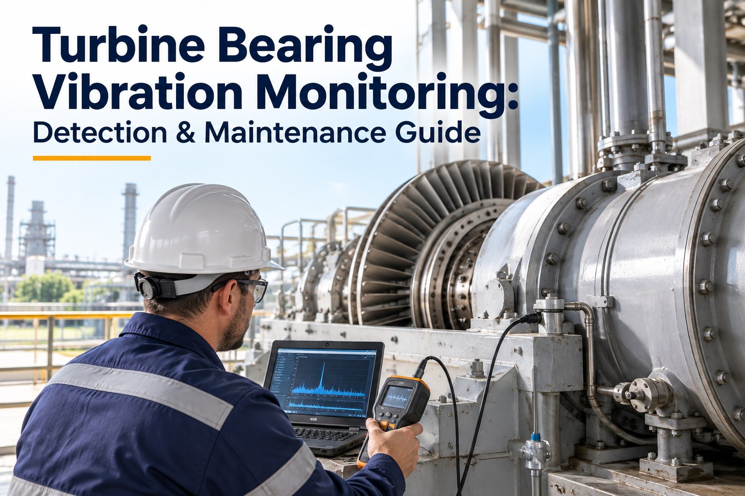
Bearing vibration is the single most actionable real-time indicator of turbine internal condition. A shift in vibration signature at any bearing position tells a specific diagnostic story — and reading that story correctly is the difference between a planned minor outage and an emergency disassembly. These are the vibration failure signatures reliability engineers must have on their radar.
| Vibration Signature |
Frequency Characteristic |
Affected Section |
Root Cause |
Action Threshold |
| 1× runspeed amplitude rise |
1× (synchronous) |
HP / IP / LP |
Mass unbalance, thermal bow, blade loss |
Alert: +25% of baseline |
| Sub-synchronous instability |
0.3–0.5× runspeed |
LP journal bearings |
Oil whirl / oil whip |
Immediate trip threshold |
| 2× runspeed component |
2× (super-synchronous) |
HP / IP |
Misalignment, rub, coupling issues |
Alert: 2× amplitude > 30% of 1× |
| High-frequency broadband |
Above 5× runspeed |
All sections |
Blade damage, partial arc steam admission |
Spectrum shift >6 dB — inspect |
| Axial vibration increase |
1× and 2× mixed |
Thrust bearing |
Thrust bearing wear, blade axial loading change |
Thrust position >±0.5 mm — trip |
OxMaint CMMS captures vibration alert events as timestamped records linked to the specific bearing position and work order history — giving the next overhaul team a complete vibration audit trail, not just the most recent reading.
Blade Condition
Blade Erosion Progression and Inspection Trigger Points
Blade erosion in the LP section is not a linear process. It accelerates as the boundary between steam and moisture moves upstream during load cycling, and the last two stages of the LP section bear the brunt. Missing the first erosion inspection window compounds repair cost by 3–5 times when blade replacement becomes mandatory rather than optional.
Stage 1
0 – 20,000 hrs
Surface Pitting
Leading edge micro-pitting. Efficiency loss less than 0.5%. Polishing at minor outage sufficient.
Low Risk
Stage 2
20,000 – 40,000 hrs
Leading Edge Erosion
Material removal at leading edge up to 3mm. Efficiency loss 1–2%. Stellite shield inspection critical.
Moderate — Plan Inspection
Stage 3
40,000 – 60,000 hrs
Substrate Exposure
Shield fully eroded, base alloy exposed. Efficiency loss 2–4%. Blade replacement at next planned outage.
High — Replace at Outage
Stage 4
60,000+ hrs without intervention
Blade Fracture Risk
Stress concentration at erosion notch. Foreign object potential. Risk of catastrophic failure. Forced outage imminent.
Critical — Immediate Action
CMMS-Backed Turbine Reliability
Track Every HP, IP & LP Inspection in One System — With RUL and Campaign Records Built In
OxMaint links vibration trending, blade inspection findings, seal condition records, and EOH counters to asset-level PM schedules — so your next overhaul campaign starts with complete context, not scattered spreadsheets.
Shaft Seals
Shaft Seal Condition: The Hidden Heat Rate Killer
Shaft gland seals prevent steam leakage at the rotor entry and exit points of each section. When seals degrade, steam bypasses the blading, heat rate rises, and — in the HP section — superheated steam contacts bearing housings and oil systems. Seal condition monitoring is one of the highest return-on-investment PM activities in turbine maintenance, yet it is frequently deferred.
Labyrinth Seals
HP & IP Sections
+0.3–0.8% heat rate per worn stage
Fin clearance increases from 0.3mm design to 0.8–1.2mm after 40,000 hours. Steam leakage grows non-linearly. Boroscope inspection + cold clearance measurement at each major outage.
PM Trigger: Every major outage / clearance >0.7mm
Carbon Ring Seals
LP Section Ends
Air in-leakage raises condenser back-pressure 2–5 mbar
Carbon segments wear unevenly due to rotor runout. Broken segments allow air ingress to condenser, raising back-pressure and costing 0.5–1.5 MW at full load. Segment replacement at minor outage.
PM Trigger: Condenser dissolved oxygen >10 ppb or back-pressure rise
Brush Seals
Modern HP Retrofits
50–75% lower leakage vs labyrinth when new
Bristle pack wear accelerates after thermal transients. Inspection requires rotor extraction. Run-in period of 500 hours before baseline clearance measurement is taken.
PM Trigger: 48,000 hours or after any forced outage event
CMMS & Records
What a Complete Steam Turbine CMMS Record Looks Like
The value of a CMMS for turbine maintenance is not in scheduling alone — it is in the asset memory it builds across overhaul cycles. A reliability engineer preparing a major campaign should be able to pull the last three outage inspection findings, vibration trend history, EOH counter, and previous blade measurements without calling three different departments. This is what an OxMaint turbine asset record contains.
Record Category
What OxMaint Captures
Why It Matters for Next Campaign
EOH Counter
Equivalent operating hours with starts/stops weighted
Determines inspection interval trigger — calendar hours alone mislead
Blade Inspection Findings
Stage-by-stage erosion depth, cracking, shield condition
Tracks erosion rate — predicts replacement need before next outage
Vibration History
Bearing amplitude trends by frequency component
Confirms whether post-outage balance is holding over time
Seal Clearance Records
Measured clearances vs. design spec per seal position
Allows heat rate degradation to be modelled from seal data
RUL Estimate
Condition-adjusted remaining useful life per section
Drives capital planning for rotor replacement or refurbishment
Overhaul Work Orders
Full work history with technician, date, findings, parts
Audit trail for OEM warranty, insurer, and regulator compliance
Frequently Asked Questions
Steam Turbine Maintenance — Questions Reliability Engineers Ask
What is the correct inspection interval for HP turbine blades?
HP blade inspection intervals are driven by equivalent operating hours (EOH), not calendar time. Industry standard is 24,000–32,000 EOH for the first major inspection, with EOH calculated by weighting starts, peak loads, and temperature excursions. Plants with high cycling frequency should target the lower bound.
OxMaint's EOH counter automates this calculation from operating data.
How does AGC (Automatic Generation Control) affect turbine wear?
AGC dispatch increases thermal cycling frequency significantly — each load swing adds EOH equivalents beyond simple runtime hours. Turbines operating under AGC should have EOH multipliers of 1.2–1.8× applied per start cycle depending on load ramp rate. Reliability engineers should configure
CMMS PM triggers based on AGC-adjusted EOH, not raw hours.
What vibration level is the trip threshold for steam turbines?
ISO 7919-2 defines shaft vibration trip limits for steam turbines. For machines above 1,500 rpm, the trip threshold is typically 200–250 µm peak-to-peak shaft displacement or 12–18 mm/s RMS casing velocity, depending on bearing type. Alarm setpoints should be 25% below trip levels, with trending alerts at 50% of alarm.
Can OxMaint track steam turbine overhaul campaigns across multiple units?
Yes. OxMaint supports multi-unit asset hierarchies where each turbine section — HP, IP, LP — is a separate asset with its own PM schedule, EOH counter, and inspection record.
Book a demo to see how a fleet of turbines is managed within a single plant CMMS instance.
What causes last-stage LP blade stress corrosion cracking?
Stress corrosion cracking (SCC) in LP last-stage blades results from the combination of tensile blade stress, corrosive species concentration in wet steam (chlorides, hydroxides), and blade material susceptibility. Operating in the phase transition zone (Wilson line) accelerates attack. Inspection by dye penetrant and ultrasonic testing is required at each major LP outage.
Give Your Turbine Reliability Program the CMMS Backbone It Needs
OxMaint tracks HP, IP, and LP section condition across every inspection cycle — vibration baselines, blade findings, seal clearances, and EOH-adjusted PM schedules — in one auditable system. Start a free account or book a 30-minute walkthrough with your process details in hand.

.png)
.png)


