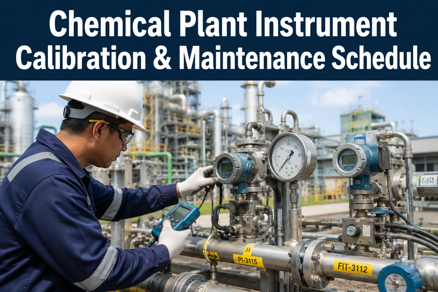
A modern chemical plant runs on somewhere between three and eight thousand field instruments, and every one of them belongs on a calibration and maintenance schedule tied to how critical it is to safety, throughput, and product quality. A SIL-3 pressure transmitter on a reactor high-pressure trip carries proof-testing obligations under IEC 61511 that a general-purpose gauge does not. A Coriolis meter on the custody transfer skid has fiscal accuracy requirements that a raw-water flow indicator does not. A pH analyzer on the neutralization loop drifts and coats on a completely different clock than a differential-pressure level transmitter on a solvent tank. Treating them all the same wastes calibration hours on non-critical monitoring while under-testing the instruments that will decide whether a runaway reaction is stopped or a batch is scrapped. Oxmaint is the maintenance software that separates the fleet by criticality tier, matches PM cadence to actual risk, holds SIL proof test records to IEC 61511, and generates the audit-ready documentation the plant's process safety program depends on. Start a free Oxmaint trial to run instrument calibration on the CMMS, or book a demo to see the CMMS mapped to your chemical plant's instrument fleet.
Chemical Plant · Instrumentation · Calibration CMMS
Chemical Plant Instrument Calibration & Maintenance Schedule — The 2026 Guide
Flow meters, pressure transmitters, level sensors, temperature elements, and process analyzers — with SIL proof testing, custody transfer accuracy, and process-critical cadence on one CMMS.
-
3,000–8,000
field instruments in a typical modern chemical plant — every one on a schedule
-
6–12 Mo
SIL 3 proof test interval under IEC 61511 — non-negotiable, no matter how well the instrument reads
-
5 Types
instrument categories cover the working fleet — flow, pressure, level, temperature, analyzer
-
4 Tiers
criticality tiers drive interval assignment — SIS-SIL, custody, process critical, monitoring
Why Chemical Plant Instruments Are a Special Case
Four Conditions That Make Chemical Plant Instrument Programs Different
Every process plant calibrates instruments. Chemical plants are different because the readings feed safety instrumented systems that protect against runaway reactions, custody transfer meters that account for millions of dollars a month in feedstock and product, environmental compliance monitoring, and process control loops where a 2% error becomes an off-spec batch. Understanding the four defining conditions is the starting point for a real program.
-
01
Safety Instrumented Obligations
Runaway reaction protection, high-pressure trips, emergency shutdown loops. IEC 61511 mandates proof testing at intervals tied to the SIL rating — with no exceptions for stable instruments.
-
02
Fiscal Accuracy on Custody Transfer
Feedstock in and product out both meter across custody transfer skids. Every 0.1% drift is direct dollar exposure. API MPMS calibration requirements are tighter than process-side instruments.
-
03
Hazardous, Corrosive, Fouling Services
Analyzers coat. Impulse lines plug. Wet legs freeze. Sample systems clog. The failure modes are not sensor drift — they are service-driven and category-specific.
-
04
Continuous Operation
A chemical plant runs 24/7. Calibrations mostly happen while the plant is running, using loop bypass, redundancy, or short trip strokes — a discipline that requires structured planning inside the CMMS.
The Five Instrument Categories
The Working Fleet Splits Into Five Category Groups
Every field instrument in a chemical plant belongs to one of five category groups, and every group has its own dominant technology types, failure modes, and calibration approach. Oxmaint holds category and technology type against every instrument record — so the correct PM template and calibration method apply automatically.
-
C1
Flow Meters
Volume, mass, and standardized flow measurement across every feed, product, utility, and vent stream.
Types: Coriolis, magnetic, orifice/DP, ultrasonic, vortex, turbine, positive displacement
-
C2
Pressure Transmitters
Static and differential pressure on every vessel, line, filter, exchanger, and trip circuit. The most numerous category by count.
Types: gauge, absolute, differential, remote seal, seismic transmitter
-
C3
Level Sensors
Vessel level, interface level, hopper level. Choice of technology depends heavily on service conditions and process material.
Types: guided-wave radar, non-contact radar, DP-level, ultrasonic, tuning fork, RF capacitance, servo
-
C4
Temperature Elements
Thermowell-mounted sensors on every reactor, exchanger, distillation stage, and jacket. Frequently SIL-rated on high-consequence circuits.
Types: RTD (Pt100, Pt1000), Type-K thermocouple, IR pyrometer, surface probes
-
C5
Process Analyzers
Composition, concentration, and quality measurement. The category with the most failure modes and the shortest calibration intervals.
Types: pH, conductivity, ORP, gas chromatograph, moisture, oxygen, hydrocarbon, IR/NIR
The Criticality Tier Framework
Four Tiers That Drive Every Calibration Interval Assignment
Not every instrument earns the same PM attention. The single most important discipline in a chemical plant instrument program is putting every device into one of four criticality tiers — because the tier drives the interval, the method, and the documentation standard. Oxmaint stores the tier as a required field on every instrument record.
SIS / SIL-Rated
Instruments in Safety Instrumented Functions under IEC 61511. Proof-test intervals set by the SIL calculation — SIL 3 typically 6 to 12 months, SIL 2 typically annual to 2-year.
Standard: IEC 61511 / ISA S84
Custody Transfer
Fiscal metering skids. Feedstock in, product out. Every 0.1% drift is direct dollar exposure. Tightest tolerance requirements in the plant.
Standard: API MPMS, ISO 5024
Process Critical
Instruments in control loops where accuracy directly affects product quality, yield, or reactor stability. Calibrated annually against traceable standards.
Standard: ISA RP 105
Monitoring
Non-critical readings — utility indicators, secondary redundant sensors, informational-only gauges. Extended intervals justified by risk assessment.
Standard: Risk-based, documented rationale
Category-Specific Failure Modes
How Each Category Actually Fails in Service
Sensor drift is not the dominant chemical plant failure mode — service condition failures are. Impulse lines plug. Analyzer sample systems foul. Wet legs freeze. Level probes coat. Recognizing the category-specific failure signature is what turns a calibration event into a root-cause fix instead of another band-aid. Every failure inside Oxmaint carries the mode as a structured field.
-
Flow Meters
DP impulse line plugging (winter). Coriolis vibration coupling to piping. Magnetic meter liner damage from abrasive slurry. Wet-leg freezing on cryogenic service.
-
Pressure Transmitters
Impulse tubing plugging from wax, hydrate, or solids. Seal oil migration in remote-seal transmitters. Zero drift on differential-pressure applications.
-
Level Sensors
Radar probe coating in polymer service. DP-level wet-leg boil-off. Tuning fork buildup in slurry service. Foam interference on radar and ultrasonic.
-
Temperature Elements
Thermowell erosion in high-velocity streams. Vibration fatigue at reactor nozzles. RTD drift after thermal cycling. Loose or damaged wiring at head.
-
Process Analyzers
Sample system fouling and blockage. pH electrode reference junction poisoning. GC column degradation. Analyzer sheltering climate drift.
The Proof Test Reality
Under IEC 61511, a SIL 3 Instrument Must Be Proof Tested Whether It Reads Perfectly or Not
Proof testing is not calibration. Calibration checks accuracy. Proof testing verifies the instrument will actually cause the safety function to execute on demand — including the logic solver and the final element. A perfectly accurate SIL 3 pressure transmitter that has not been proof tested inside its interval is an IEC 61511 compliance failure and a process safety exposure. Oxmaint holds proof test intervals against every SIS instrument and blocks deferral without documented risk sign-off.
Calibration vs Proof Testing
Two Different Disciplines, Two Different Records
Chemical plants routinely conflate routine calibration with SIS proof testing — a category error that leaves both jobs incomplete. Below is the working distinction. Oxmaint keeps calibration and proof test as separate work order types with different templates, different intervals, and different documentation requirements.
| Attribute | Routine Calibration | SIS Proof Test |
|---|---|---|
| Objective | Verify accuracy across measurement range | Verify safety function executes on demand |
| Scope | Sensor or transmitter alone | Full loop — sensor, logic, final element |
| Interval Driver | Drift history, criticality, service | SIL calculation, PFD budget |
| Deferral | Extendable with drift justification | Requires functional safety sign-off |
| Standard | ISO 17025, ISA RP 105 | IEC 61511, ISA S84 |
| Record | As-found, as-left, tolerance check | Full stroke, response time, bypass log |
Where Manual Programs Break
Four Gaps Every Process Safety Audit Finds First
-
01
SIL Proof Tests Treated as Calibrations
The transmitter got calibrated during turnaround. The proof test — sensor, logic, valve — never actually happened. IEC 61511 compliance gap discovered at the next PHA revalidation.
-
02
Every Instrument on the Same Interval
Tier 4 monitoring gauges calibrated annually, chewing up craft hours. Tier 3 process-critical instruments on the same annual schedule despite drift history warranting shorter intervals.
-
03
Category Failure Modes Ignored
Analyzer sample system plugged three times last quarter. Nobody fixed the root cause. Every calibration adjusts the sensor and the sample system fails again the same week.
-
04
Custody Transfer Records Fragmented
Fiscal meter calibration certificates in a binder. API MPMS proving reports somewhere else. Reconciliation with the counterparty a manual scramble every quarter.
Built for Chemical Plant Instruments
How Oxmaint Runs the Chemical Plant Instrument Fleet
-
Category-Aware Assets
Every Instrument Classified by Category and Technology
Flow, pressure, level, temperature, analyzer — with specific technology (Coriolis, magnetic, GWR, RTD, GC). Correct PM template inherits from category and tech automatically.
-
Tiered Cadence
Interval Driven by Criticality Tier
Tier 1 SIS-SIL, Tier 2 custody transfer, Tier 3 process critical, Tier 4 monitoring — each with its own default cadence, deferral rules, and documentation standard.
-
Separate Proof Tests
SIS Proof Testing as Its Own Work Order Type
Not the same as routine calibration. Full-loop scope, IEC 61511 template, functional safety approver, deferral workflow with risk assessment sign-off.
-
Failure Mode Tracking
Category-Specific Modes as Structured Fields
Impulse plugging, sample system fouling, probe coating, wet-leg boil-off. Failure mode as a categorical field per instrument — repeat patterns surface automatically.
-
Drift Trending
As-Found Data Trended Per Instrument
Every calibration cycle logs as-found and as-left. Drift trended. Stable instruments earn extended intervals. Drifting instruments get shortened intervals — data-driven, not sticker-driven.
-
Audit Package
Process Safety and Fiscal Audit Records on Demand
IEC 61511 proof test history. API MPMS custody transfer records. ISA RP 105 process instrument documentation. Every audit package pulls in one export.
Measured Outcomes
What Chemical Plants Gain When Instruments Run on Oxmaint
-
Zero
Missed Proof Test Intervals
Every SIL-rated instrument tested inside its IEC 61511 interval — no deferral without documented functional safety sign-off.
-
30–40%
Craft Hour Recovery
Tier 4 monitoring instruments moved to justified extended intervals recover craft hours that were being wasted on non-critical calibrations.
-
Root-Cause
Failure Mode Fixes
Category-specific failure mode tracking surfaces sample system, impulse line, and coating problems that were previously masked as sensor drift.
-
One Click
Audit Package Export
PHA revalidation, fiscal audit, PSSR — every documentation package exports in one action, no scrambling through binders and mailboxes.
Frequently Asked
Chemical Plant Instrument & CMMS Questions
What is the SIL 3 proof test interval under IEC 61511?
There is no fixed interval — IEC 61511 does not specify one. The interval is derived from the SIL calculation and the target Probability of Failure on Demand (PFDavg) allocation for the specific safety function. In practice, SIL 3 loops typically land on 6 to 12 month intervals, SIL 2 on 12 to 24 months, and SIL 1 on 24 to 48 months, but the actual interval must be justified by the SIL calculation for that loop. Sign up for Oxmaint to track SIS proof test intervals against every SIF loop.
Is a routine calibration the same as a proof test?
No. A calibration verifies the sensor or transmitter reads accurately across its measurement range. A proof test verifies the entire safety loop — sensor, logic solver, and final element (typically the ESD valve or motor trip) — actually executes the safety function on demand. A perfect calibration record does not satisfy an IEC 61511 proof test obligation. Oxmaint keeps them as separate work order types with different templates.
Why should intervals differ across the four criticality tiers?
Because the consequence of failure differs. A SIL-3 pressure transmitter on a runaway reaction protection loop demands 6 to 12 month proof testing regardless of stability. A monitoring gauge on a utility line does not — extended intervals save craft hours with negligible risk increase. Assigning every instrument the same interval either wastes craft time on Tier 4 or under-tests Tier 1. Book a demo to see tiered cadence assignment in Oxmaint.
How does the software surface category-specific failure modes?
Every failure event on an instrument records the category and failure mode as structured fields — impulse plugging, sample system fouling, probe coating, wet-leg boil-off, thermowell erosion, sensor drift. Reports group by mode across the instrument population, surfacing whether a service condition or installation issue is driving repeat failures across multiple instruments in the same category. Sign up for Oxmaint to run category-specific failure mode tracking on every instrument.
Classify · Test · Prove
Every Process Safety Finding on Instrument Calibration Was Preventable Inside a Structured Program
The proof test that got confused with a calibration. The Tier 4 monitoring gauge chewing up hours that Tier 1 SIS loops needed. The failure mode that kept repeating because nobody tracked it as a data field. The custody transfer certificate nobody could find. Every one closed by a CMMS that separates the fleet by category and tier, matches cadence to actual risk, and holds proof test and calibration records to the standard the audit will actually check.