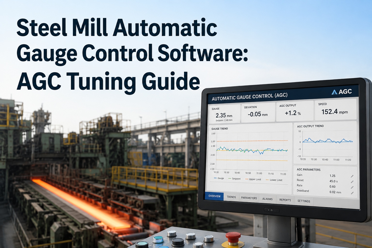
Automatic Gauge Control is what stands between a rolling mill and a coil that's out of tolerance end to end. A well-tuned AGC system can pull thickness deviations from a raw 10–30 microns down to 1–4 microns, keeping far more of every strip inside spec — but that performance is fragile. It depends on a control loop reading true signals and acting through healthy hardware, and the moment an X-ray gauge drifts, a load cell reads low, or a hydraulic capsule responds sluggishly, the tuning that was perfect last month starts fighting the mill instead of correcting it. That's the part most AGC discussions miss: gauge control is a control-theory problem sitting on top of a maintenance problem. The gains, the mill-modulus, the feedforward coefficients only work if the sensors and actuators underneath them are calibrated and responsive. This guide covers AGC the way a mill actually has to manage it: the gaugemeter principle and the three control loops, what tuning gain and reference gauge tracking really means, the head-to-tail variance problem, and how a CMMS keeps the sensors and hydraulics healthy so the control stays honest. Book a free AGC-reliability review for your mill.
AGC Is a Control Problem on Top of a Maintenance Problem
Perfect gains can't save gauge control when the X-ray sensor drifts or the hydraulic capsule lags.
1–4 μm
Thickness deviation a tuned AGC holds, down from a raw 10–30 μm
3 loops
Feedforward, feedback, and mass-flow — each correcting a different error
~100%
Of incoming thickness disturbance a self-adaptive feedforward can remove
Head/tail
Where variance concentrates — during threading and acceleration
The Gaugemeter Principle · How AGC Knows the Thickness
Most AGC rests on the BISRA gaugemeter method, and understanding it is the key to tuning it. The mill can't measure strip thickness directly inside the roll bite, so it infers it — from how much the mill stretches under load.
S
Unloaded roll gap. The position of the rolls with no strip in the bite, set by the screw-down or hydraulic capsule and read by a position transducer.
P
Rolling force. The separating force the strip generates, measured by load cells. Under load the mill stretches, so actual gap exceeds the set gap.
Km
Mill modulus. The stiffness of the mill stand — how much it deflects per unit of force. The calibration constant at the heart of gaugemeter accuracy.
The insight for tuning: if the load-cell signal, the position reading, or the mill-modulus value is wrong, the inferred thickness is wrong — and the AGC will confidently correct toward the wrong number. Accuracy of the inputs is accuracy of the control.
The Three Control Loops · Each Corrects a Different Error
A modern AGC system isn't one controller — it's several loops working together, each attacking thickness error from a different direction, with bumpless transitions between them. Tuning means balancing all three.
Feedforward AGC
Acts before the error reaches the bite
Reads entry thickness deviation and entry speed ahead of the roll gap and pre-corrects the gap before that variation is rolled. Self-adaptive feedforward can remove nearly 100% of an incoming thickness disturbance — the most powerful loop for inbound variation.
Feedback AGC
Corrects the measured exit error
Takes the exit thickness gauge reading, traces it back to the roll gap, and closes the loop to trim residual error. Because the gauge sits downstream, it needs delay compensation — often a Smith predictor — so the correction stays stable at speed.
Mass-Flow AGC
Conserves what goes in and out
Uses entry and exit speed and thickness together — since mass in equals mass out, exit thickness can be computed from the ratio and corrected fast, without waiting on the downstream gauge delay. Powerful on tandem cold mills.
Review Your AGC Signal Chain in 30 Minutes
Working session with our team — bring your mill's gauge, load-cell, and hydraulic setup. We'll map the sensors and actuators every AGC loop depends on, and show how OxMaint keeps their calibration and health scheduled so your tuning holds.
What Tuning Actually Means
Tuning AGC isn't one dial — it's balancing gain against stability across the loops, and keeping the model matched to the physical mill. Push gain too hard and the loop oscillates; too soft and error slips through. These are the levers.
01
Loop Gain
How aggressively each loop corrects a given error. High gain responds fast but risks oscillation and instability; low gain is stable but leaves residual deviation. The core trade-off.
02
Mill Modulus Match
The Km value in the gaugemeter must match the stand's true stiffness. A mismatch — from worn components or wrong calibration — makes every inferred thickness biased and the correction wrong.
03
Delay Compensation
The exit gauge is downstream, so feedback lags. A Smith predictor or speed-scheduled parameters keep the loop stable as mill speed changes — critical during acceleration.
04
Roll Eccentricity Compensation
Out-of-round or eccentric rolls inject a periodic thickness error the gaugemeter can misread as real. Eccentricity compensation filters it so AGC doesn't chase a false signal.
The Head-to-Tail Problem · Where Variance Hides
Even a well-tuned AGC struggles at the two moments it matters most — the very start and end of a strip. This is where off-gauge length concentrates, and why threading and acceleration get special tuning attention.
HEAD
Threading — AGC Not Yet Full Authority
As the strip threads, tension and gauge loops are still establishing and the head end often runs thick before the loop takes full control. Threading-mode tuning minimizes the off-gauge lead length.
BODY
Steady-State — AGC at Full Correction
Through the body, all loops run at authority and thickness holds tightest — this is where AGC delivers the 1–4 micron control that keeps the bulk of the coil in spec.
TAIL
Acceleration & Tail-Out — Speed Effects Fight the Loop
During acceleration the speed effect and AGC correction can compound, and at tail-out tension changes disturb gauge before the loop recovers. Speed-scheduled gains keep the tail in tolerance.
The Maintenance Layer · Why Tuning Drifts Out
Here's the connection most AGC programs overlook: every term in the gaugemeter and every loop input comes from a physical sensor or actuator, and when those degrade, the control degrades — no matter how well it was tuned. Tuning doesn't drift on its own; the hardware underneath it does.
X-Ray / Isotope Thickness Gauges
Feed the feedback loop. Drift or misalignment feeds the loop a false exit thickness — so AGC corrects the mill toward the wrong target. Scheduled calibration keeps the reference honest.
Load Cells & Position Transducers
Provide P and S in the gaugemeter. A load cell reading low or a transducer out of zero biases the inferred thickness directly — the gaugemeter is only as good as these two signals.
Hydraulic Capsule & Servo Valves
The actuator that moves the gap. A sluggish capsule or worn servo valve adds lag the loop can't tune away — AGC commands a correction the hardware delivers too slowly, and gauge suffers.
How OxMaint Keeps AGC Control Honest
OxMaint doesn't tune the loop — it keeps the hardware the loop depends on healthy and calibrated, on schedule, so the control your engineers set actually holds. Structured assets, sensor-calibration PM, condition monitoring, and reliability reporting from one dashboard on desktop or mobile.
Calibrate
Gauge & Sensor Cadence
Schedule X-ray gauge, load-cell, and position-transducer calibration on a defined cadence — so every gaugemeter input stays true and the reference gauge holds.
Monitor
Hydraulic & Servo Health
Track hydraulic capsule response, servo-valve condition, and oil cleanliness with IoT triggers — catch the lag that degrades AGC before it shows up as off-gauge product.
Detect
Drift & Deviation Alerts
A calibration due-date, a load-cell trend, or a hydraulic response drift fires an alert tied to the asset — before the control loop starts correcting toward a false signal.
Trigger
Auto-Generated Work Orders
A due calibration or a drift alert converts to a prioritized work order with procedure and parts staged — mobile-first, with offline mode and QR asset tags on the mill floor.
Correlate
Gauge Variance to Asset
Link thickness-variance events back to the sensor or actuator behind them, so a recurring gauge problem gets root-caused to hardware, not endlessly re-tuned.
Report
Reliability & Compliance
Calibration records, asset history, and reliability dashboards in one place, with SAP and Maximo overlay — audit-ready across one mill or a global network.
Keep the Tuning You Set From Drifting Away
Stop re-tuning AGC to chase a drifting sensor. See how OxMaint keeps every gauge, load cell, and hydraulic actuator calibrated and healthy on schedule — so your gauge control holds head to tail. Free forever plan available.
Frequently Asked Questions
What is Automatic Gauge Control (AGC) in a steel mill?
AGC is the closed-loop control system that regulates the thickness (gauge) of strip or plate at a rolling mill's exit by continuously adjusting the roll gap. It monitors thickness — usually inferred from rolling force and roll position via the gaugemeter method, and measured directly by X-ray gauges — and drives the screw-down or hydraulic capsule to hold the target thickness. A well-tuned AGC system can reduce thickness deviations from a raw magnitude of 10–30 microns down to 1–4 microns, keeping far more of every coil within tolerance. Modern systems combine feedforward, feedback, and mass-flow loops with roll-eccentricity compensation, and keep running until the mill stops to hold gauge across the whole strip.
Book a reliability review.
What is the gaugemeter (BISRA) principle?
The gaugemeter or BISRA AGC method infers strip thickness without measuring it directly in the roll bite. It uses the relationship h = S + P/Km, where S is the unloaded roll gap from a position transducer, P is the rolling force from load cells, and Km is the mill modulus — the stand's stiffness. Because the mill stretches elastically under rolling force, the actual gap is larger than the set gap by an amount proportional to force divided by stiffness; adding that deflection term to the position signal yields a real-time thickness estimate used to close the control loop. The method is accurate and fast, but only as good as its inputs — which is precisely why load-cell, transducer, and mill-modulus accuracy is foundational.
What's the difference between feedforward and feedback AGC?
Feedforward AGC measures the incoming disturbance — entry thickness deviation and entry speed — ahead of the roll bite and pre-adjusts the gap before that variation is rolled, so it prevents the error rather than reacting to it; a self-adaptive feedforward can remove nearly 100% of an incoming thickness disturbance. Feedback AGC works the other way: it reads the actual exit thickness downstream, traces it back to the roll gap, and corrects the residual error that got through. Because the exit gauge is physically downstream, feedback carries a transport delay and needs compensation — often a Smith predictor — to stay stable at speed. Mass-flow AGC adds a third path, computing exit thickness from the conservation of mass between entry and exit. The three are used together with bumpless transitions.
Sign up free to track the signal chain.
Why does head-to-tail thickness variance happen?
Because the two ends of a strip are rolled under transient conditions the AGC hasn't fully stabilized. At the head, during threading, the tension and gauge loops are still establishing authority, so the lead end often runs thick before the loop takes full control. At the tail, during acceleration to run speed and at tail-out, speed effects and tension changes disturb the gauge — and notably, AGC corrections for thick strip and the speed effect can compound to drive the strip too thin before the loop recovers. The strip also moves through the mill fast during acceleration, so a lot of length passes before it's back on gauge. Dedicated threading-mode and speed-scheduled tuning target exactly these transients to minimize off-gauge lead and tail length.
How does maintenance affect AGC performance?
Fundamentally — because every AGC input comes from a physical device that can degrade. The gaugemeter depends on load cells (rolling force) and position transducers (roll gap); the feedback loop depends on X-ray or isotope thickness gauges; and every correction is executed by a hydraulic capsule and servo valves. If a load cell reads low, a gauge drifts or misaligns, or a hydraulic capsule responds sluggishly, the loop is either working from a false signal or unable to act fast enough — and no amount of gain tuning fixes a hardware problem. This is why AGC that was perfectly tuned can slowly degrade: the tuning didn't change, the sensors and actuators did. Scheduled calibration and condition monitoring of that signal-and-actuation chain, managed in a CMMS, is what keeps the control honest over time.