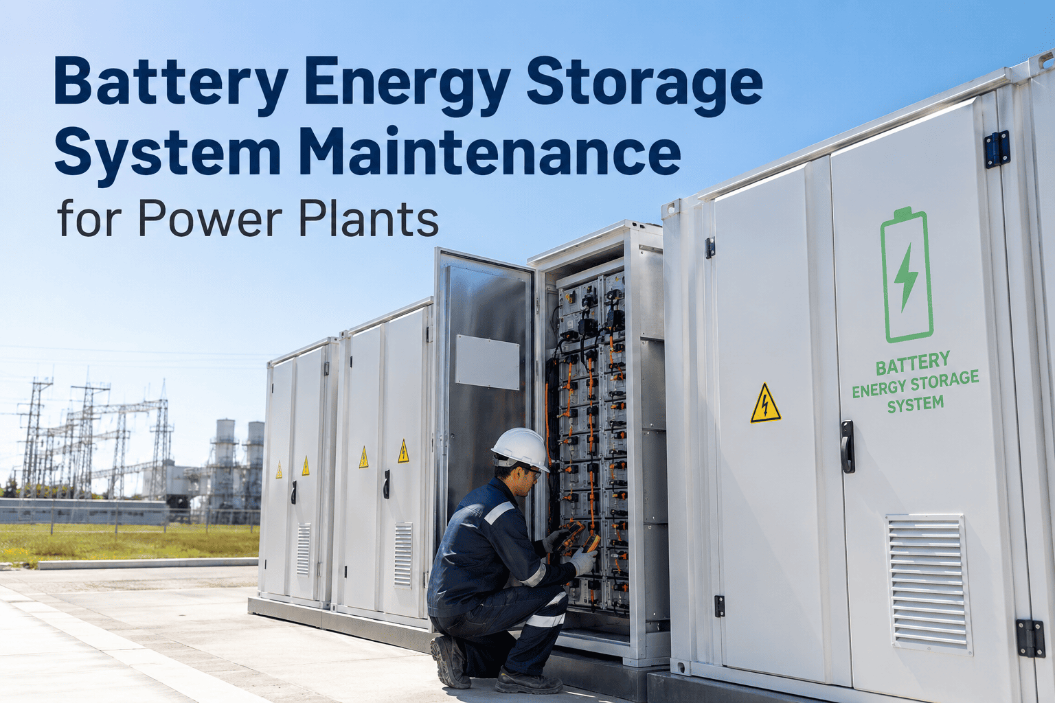
Station battery banks and DC distribution systems are the invisible backbone of power plant protection — when AC power fails, these systems must deliver precise, uninterrupted voltage to trip breakers, power relay panels, and sequence emergency shutdowns in milliseconds. A degraded battery cell or failed charger discovered during an emergency rather than during routine inspection can cascade into uncontrolled equipment damage, reactor protection failure, or extended forced outage. OxMaint's preventive maintenance platform transforms battery inspection from clipboard-and-clipboard routine into a digitally tracked, trend-analyzed program that catches capacity fade, electrolyte issues, and charger faults before they compromise emergency power reliability.
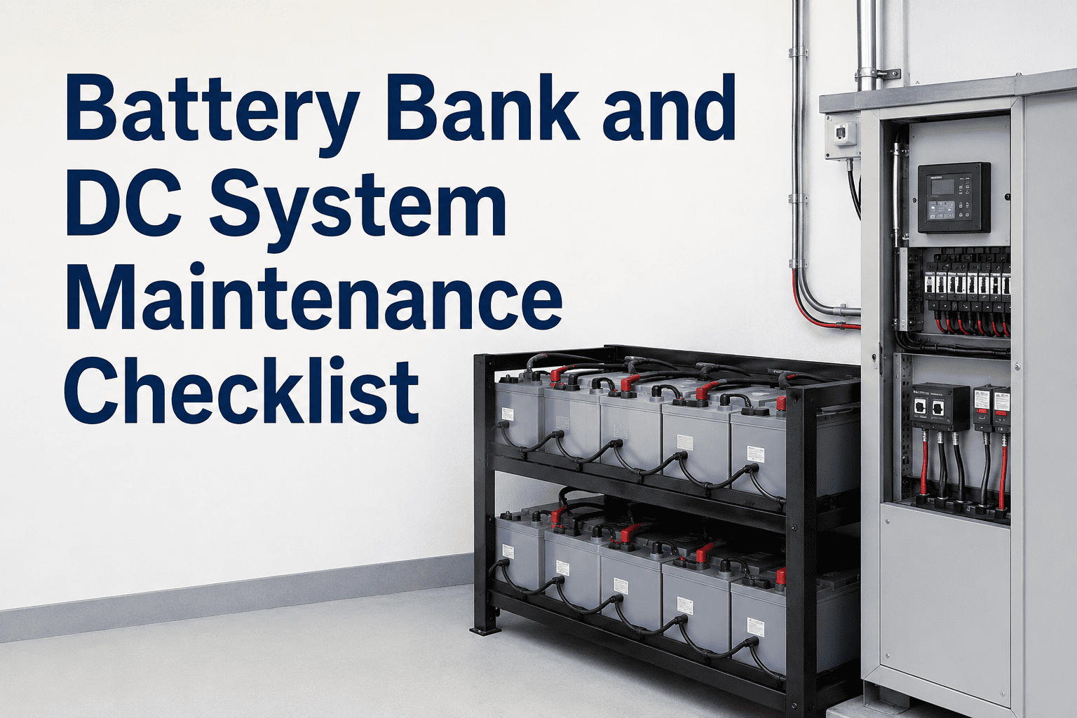
Battery Bank and DC System Maintenance Checklist
A structured inspection and testing protocol covering voltage verification, load testing, electrolyte management, charger health, and DC distribution integrity — for substation, power plant, and industrial backup power systems.
Individual Cell Voltage and Visual Inspection
Individual cell monitoring reveals capacity imbalance invisible at the string level. Voltage variation between cells is the earliest detectable indicator of impending capacity failure and must be trended over time.
Load Testing and Capacity Verification
Load testing is the definitive measure of battery capacity and the only method that confirms the system will perform when required. Capacity below 80% of rated ampere-hour value indicates replacement is required before next scheduled maintenance cycle.
Track Every Cell. Predict Every Failure.
OxMaint logs individual cell voltages, load test results, and charger readings into a unified trending system — automatically flagging deviating cells, calculating capacity trends, and generating replacement forecasts before backup power reliability is compromised.
Electrolyte Level and Specific Gravity Testing
Electrolyte condition directly reflects battery state of health and charge. Specific gravity measurement detects sulfation, stratification, and acid loss that accelerate cell degradation and reduce available capacity during emergencies.
Charger Inspection and DC Distribution Verification
The battery charger is the continuous life-support system for the battery bank. Incorrect float voltage, failed rectifiers, and poor regulation silently degrade battery health or leave the system uncharging between maintenance visits.
Battery Maintenance Program Metrics
| Performance Metric | Calculation | Target | Frequency |
|---|---|---|---|
| Cell Voltage Deviation Rate | Cells outside tolerance ÷ total cells | Below 2% | Monthly |
| Battery Capacity Rating | Measured capacity ÷ nameplate capacity | Above 80% | Annual |
| Charger Uptime | Hours in float mode ÷ total hours | Above 99.5% | Monthly |
| Inspection Schedule Compliance | Completed inspections ÷ scheduled | 100% | Monthly |
| DC Ground Fault Duration | Hours with uncleared ground fault | Zero | Weekly |
Battery Bank Maintenance Questions
How often should station batteries receive a full load test?
IEEE 450 recommends performance testing every two years for vented lead-acid batteries and annual modified performance tests for batteries showing any cell voltage deviation. Batteries older than 10 years should be tested annually regardless of visual condition. OxMaint automates test scheduling based on battery age and last test results.
What is the correct float voltage for a 125V station battery?
A 60-cell, 125V nominal battery should be floated between 132 and 135 volts (2.20 to 2.25 volts per cell) at 25 degrees Celsius. Temperature compensation is critical — float voltage should be reduced by 3mV per cell per degree Celsius above 25 degrees to prevent overcharging.
When should a battery cell be replaced rather than the entire string?
Individual cell replacement is economical when fewer than 10% of cells show degradation, the rest of the string tests above 90% capacity, and the battery is within the first half of its design life. When more than 20% of cells are defective or the string has exceeded 15 years, full string replacement is more reliable and cost-effective.
How does a DC ground fault affect protection system reliability?
A single ground fault does not immediately cause failure but creates the condition where a second ground fault on the opposite bus can short the DC supply, cause spurious relay trips, or prevent protective relays from operating when needed. Ground faults must be cleared within 24 hours of detection.
Can VRLA batteries use the same maintenance checklist as vented lead-acid?
VRLA (valve-regulated lead-acid) batteries require modified procedures — electrolyte inspection is not applicable, and internal resistance testing is the primary health indicator. IEEE 1188 governs VRLA maintenance and requires ohmic testing rather than gravity measurements. OxMaint supports both battery types with separate checklist templates.
Your Emergency Power System Deserves Better Than a Spreadsheet.
OxMaint gives electrical maintenance teams a complete DC system health tracking platform — individual cell trending, load test history, charger performance logs, and automated replacement forecasting. Know your battery capacity before the next emergency demands it.