A feedwater pump failure during peak generation is not a maintenance inconvenience — it is a forced unit trip. Boiler feed pumps operate at 150–350 bar discharge pressure, 180°C fluid temperature, and rotational speeds above 3000 RPM: conditions that turn early warning signs into catastrophic failures within hours if the right monitoring is not in place. The data is consistent across the industry: bearing failures account for 34% of feedwater pump outages, mechanical seal failures account for 28%, and cavitation-related impeller damage accounts for a further 19% — all conditions that vibration monitoring, seal health checks, and bearing analytics can detect weeks before failure occurs. This case study details how OxMaint's Predictive Maintenance AI module connects sensor streams to automated work order triggers, enabling maintenance teams to act on data rather than react to breakdowns. Start your free OxMaint trial and deploy your first feedwater pump predictive maintenance workflow today, or book a live demo to see real pump condition dashboards in action.
Case Study · Pump Systems
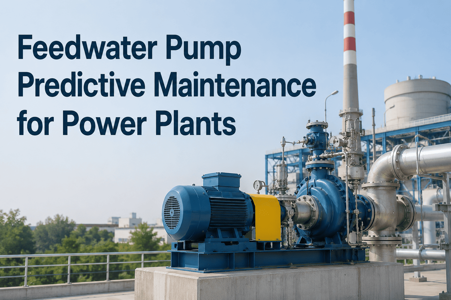
Feedwater Pump Predictive Maintenance: How Data-Driven Teams Stop Failures Before They Happen
Vibration monitoring · Seal health analytics · Bearing diagnostics · CMMS work order triggers
34%
of BFP failures — bearing origin
28%
of BFP failures — mechanical seal
19%
of BFP failures — cavitation damage
6–8 wk
Advance warning with vibration PdM
The Cost of a Boiler Feed Pump Failure
Understanding what a BFP failure actually costs is the clearest argument for a predictive maintenance investment. The numbers below reflect typical power plant economics — not worst-case scenarios.
Direct Repair Cost
$80,000 – $250,000
Bearing replacement and shaft regrind
Mechanical seal overhaul or replacement
Impeller erosion repair or replacement
Casing inspection and pressure testing
Lost Generation Revenue
$50,000 – $400,000/day
Unit trip or load reduction during BFP outage
Replacement power purchase on grid
Penalty payments for capacity shortfall
Typical BFP repair duration: 3–14 days
Hidden Costs
Often exceeds direct cost
Boiler pressure chemistry upset from abrupt shutdown
Turbine thermal shock from rapid load change
Overtime and emergency contractor mobilization
Regulatory reporting for forced outage events
Failure Mode Deep Dive: Where BFPs Actually Fail
Stage 1
Early Defect
4–8 weeks before failure
High-frequency AE (ultrasonic) detects subsurface micro-cracking. No change in overall vibration level. Only detectable with >10 kHz accelerometer or AE sensor.
OxMaint Action: Flag for inspection at next opportunity
Stage 2
Developing Fault
2–4 weeks before failure
BPFI / BPFO frequency sidebands appear in vibration spectrum. Bearing temperature begins trending upward — 5–15°C above baseline. Audible only at close range.
OxMaint Action: Create priority work order — plan bearing replacement in next scheduled window
Stage 3
Advanced Fault
3–10 days before failure
Overall vibration rises above ISO Zone B. Bearing temperature increases sharply — 20–40°C above baseline. Audible rumble from pump end. Oil contamination with metallic particles.
OxMaint Action: Immediate work order — expedite shutdown for repair
Stage 4
Catastrophic
Hours — unit trip
Bearing cage collapse. High vibration triggers protection trip. Shaft damage, seal damage, and casing scoring common at this stage. Repair time 2–4x longer than if caught at Stage 2.
OxMaint Action: Emergency work order — extended outage and forensic analysis
Monitoring Technology: What to Measure and Where
| Failure Mode |
Monitoring Technology |
Measurement Point |
Alert Threshold |
Detection Lead Time |
| Rolling Bearing Wear |
Accelerometer (BPFI / BPFO analysis) |
Drive-end and non-drive-end bearing housing |
ISO 10816-7 Zone C boundary; BPFO sideband >2x baseline |
2–6 weeks |
| Mechanical Seal Failure |
Seal flush temperature + leakage flow sensor |
Seal flush piping and gland drain |
>80°C flush temp or >2x normal flush flow |
Days to weeks |
| Cavitation |
Acoustic emission (AE) sensor |
Pump casing — suction-side |
AE RMS rise >6 dB from quiet baseline |
Immediate — real-time |
| Shaft Misalignment |
Vibration — 1x and 2x RPM analysis |
Both radial axes at each bearing |
2x component >40% of 1x amplitude |
Days (progressive) |
| Impeller Erosion |
Differential pressure transmitter |
Suction and discharge tapping points |
>5% head loss from duty curve at constant flow |
Weeks to months |
| Lube Oil Degradation |
Oil particle counter / viscosity sensor |
Inline on lube oil circuit return |
ISO 4406 code >18/16/13 or viscosity >±10% of spec |
Weeks (trending) |
OxMaint Predictive AI: From Sensor Alert to Work Order in Minutes
When your vibration sensor crosses a threshold, OxMaint automatically creates a prioritized work order, assigns the right technician, attaches the relevant SOPs, and logs the alert against the pump's complete maintenance history — all without manual intervention.
Mechanical Seal Health: The Most Neglected Monitoring Point
Mechanical seal failures are responsible for 28% of BFP outages — and the majority are preceded by measurable, detectable warning signals that most plants are not currently monitoring. Seal health monitoring is the highest-return, lowest-cost addition to any feedwater pump PdM program.
01
Seal Flush Temperature Rise
Temperature above 75°C in the seal flush circuit indicates seal face friction from insufficient lubrication, dry running, or face contamination. Detectable 2–4 weeks before leakage begins.
02
Increased Flush Flow Rate
A doubling of normal flush flow rate — measured at the throttle bush — indicates primary seal face opening under pressure cycling. Plan seal replacement at next planned outage.
03
Vibration at Seal Frequency
Vibration components at 1x RPM with phase shift indicate shaft runout at the seal face — often caused by bearing-induced misalignment that loads the seal unevenly.
04
Buffer / Barrier Pressure Loss
For dual pressurized seal arrangements (Plan 53), dropping buffer fluid pressure indicates leakage across the inboard face. Measurable weeks before external process fluid leakage occurs.
Plan 11
Flush from pump discharge to seal chamber. Monitor: flush orifice pressure drop and temperature.
Plan 23
Recirculation from seal chamber through cooler. Monitor: cooler outlet temperature and flow.
Plan 53A/B
Pressurized dual seal — barrier fluid at higher pressure. Monitor: buffer pressure and fluid level/consumption.
Plan 54
External pressurized barrier fluid system. Monitor: supply flow, pressure, and return temperature.
OxMaint stores the seal plan for each pump and maps monitoring parameters to the correct alert thresholds automatically.
Bearing Analytics: From Vibration Data to Remaining Useful Life
Bearing Defect Frequency Reference for a Typical BFP Rolling Element Bearing
BPFO
Ball Pass Frequency — Outer Race
= (N/2) × RPM × (1 − Bd·cos(α)/Pd)
Outer race defect — most common bearing fault. Look for harmonics at 2×, 3×, 4× BPFO with sidebands at 1× RPM.
BPFI
Ball Pass Frequency — Inner Race
= (N/2) × RPM × (1 + Bd·cos(α)/Pd)
Inner race defect — typically 1× RPM sidebands around BPFI peak. Indicates localized inner race spalling.
BSF
Ball Spin Frequency
= (Pd/2Bd) × RPM × (1 − (Bd·cos(α)/Pd)²)
Rolling element (ball/roller) defect. Sub-harmonics of BSF with 1× cage frequency sidebands — indicates surface pitting.
FTF
Fundamental Train Frequency (Cage)
= (RPM/2) × (1 − Bd·cos(α)/Pd)
Cage defect or lubrication failure. Sub-synchronous frequency — 0.38–0.46× RPM for most bearings. Often first indicator of lube degradation.
OxMaint Remaining Useful Life Trending
Healthy Baseline
0–4 wk
Monitor — AE elevated
4–8 wk
Plan Replacement
2–4 wk
Expedite Shutdown
3–10 days
Failure Zone
Hours
OxMaint Work Order Trigger Workflow
1
Sensor Threshold Breach
Vibration, temperature, AE, or process sensor exceeds configured threshold. OxMaint receives the alert via IoT integration within seconds.
2
Automatic Work Order Creation
OxMaint creates a prioritized work order linked to the specific pump asset, pre-populated with the failure mode, SOP, and required parts list.
3
Technician Assignment & Notification
The work order is pushed to the assigned technician's mobile device with full asset history, previous maintenance records, and measurement baselines.
4
Inspection & Data Capture
Technician completes inspection, records findings, attaches photos, and updates sensor baseline readings. All data stored against the asset in OxMaint.
5
Trend Analysis & Next Action
OxMaint updates the condition trend, recalculates alert thresholds if baseline has changed, and schedules the next inspection interval automatically.
Frequently Asked Questions
How is vibration monitoring different for vertical vs horizontal feedwater pumps?
Vertical BFPs require radial-only measurement at the upper and lower bearing housings since axial measurement is dominated by thrust bearing preload, not fault signatures. Horizontal BFPs need radial measurement in two planes plus axial at the thrust bearing. OxMaint asset profiles capture pump orientation and configure measurement point requirements accordingly.
Set up your pump assets in OxMaint free.
What baseline vibration level is acceptable for a new or recently overhauled BFP?
ISO 10816-7 defines acceptable vibration for industrial pumps. For BFPs above 15 kW, Zone A (new condition) is typically below 2.3 mm/s RMS at the bearing housing. Record your baseline within 48 hours of commissioning or return to service — OxMaint automatically stores this as the comparison reference for all future readings.
Can OxMaint integrate with our existing vibration monitoring hardware?
Yes. OxMaint integrates with continuous online monitoring systems from major vendors via REST API and MQTT, and with manual route-based data collectors through CSV/Excel import or direct API connection.
Book a demo to discuss your specific hardware configuration and integration path.
How early can cavitation damage be detected on a BFP?
Acoustic emission sensors detect active cavitation in real time — meaning cavitation is identified the moment it begins, not after impeller damage has already occurred. Differential pressure trending detects gradual impeller erosion over weeks to months through head-flow curve deviation. Both methods together give the earliest possible warning.
What data should be recorded at each feedwater pump inspection?
OxMaint's BFP inspection checklist captures: overall vibration (mm/s RMS, all measurement points), bearing temperatures (drive-end and non-drive-end), seal flush temperature and flow rate, discharge pressure and differential pressure, oil level and condition, and any audible or visual anomalies — all timestamped and stored against the asset.
Access the free BFP checklist in OxMaint.
Stop Reacting to BFP Failures — Start Predicting Them with OxMaint
Connect your feedwater pump sensor data to OxMaint's predictive maintenance platform. Automated work orders, trending analytics, and complete inspection history — all in one place. Most plants deploy their first pump PdM workflow within 48 hours.