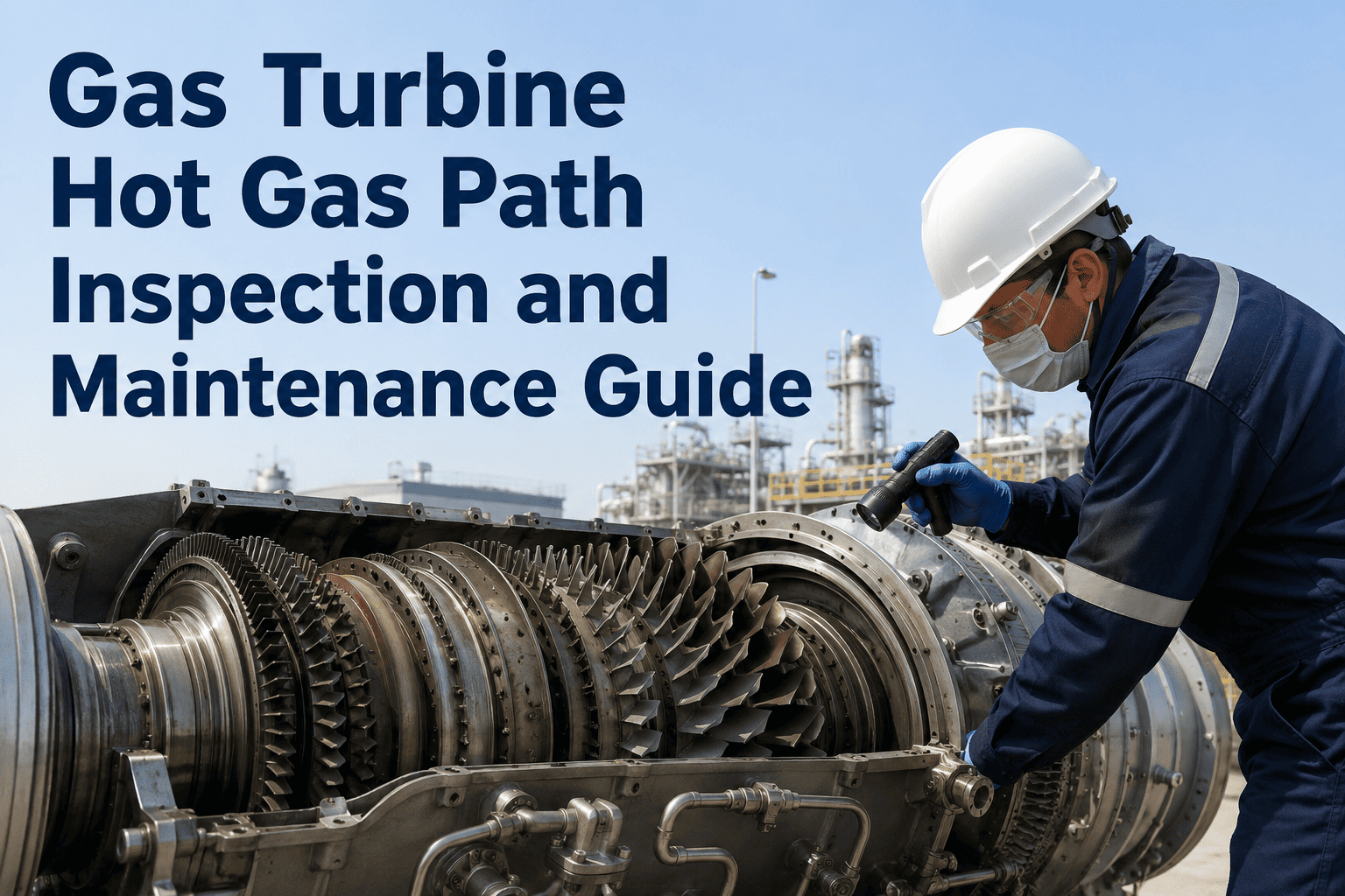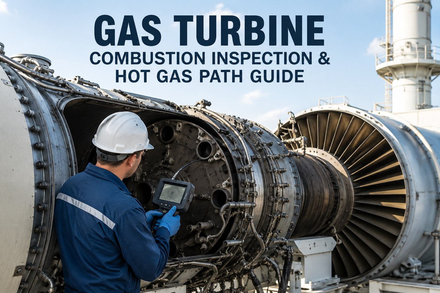
Gas turbine combustion inspections and hot gas path work scopes drive the largest parts spend and forced-outage risk in any combined-cycle or simple-cycle fleet — miss a fired-hour trigger or misclassify a borescope finding and a planned CI becomes an unplanned HGPI. This guide breaks down combustor liner wear limits, transition piece cracking patterns, first-stage nozzle and bucket findings, and the interval logic that separates a combustion inspection from a full hot gas path inspection. Track every fired hour and start against OEM intervals with OxMaint CMMS, or book a demo to see automated borescope and CI work-order generation in action.
Gas Turbine Combustion Inspection & Hot Gas Path Guide
Fired-hour and start-based triggers, combustor liner wear limits, transition piece distress patterns, first-stage blade findings, and borescope defect classification — the work-scope blueprint reliability managers use to keep hot-section outages planned, on-interval, and under budget.
CI vs. HGPI: What Drives the Work-Scope Split
OEM inspection intervals are fired-hour- and start-based — not calendar-based. The split between a combustion inspection (CI) and a full hot gas path inspection (HGPI) determines whether you pull combustor cans only or open the turbine casing and expose first-stage nozzles and buckets. Misjudge the trigger and you either overspend on an early HGPI or risk running a cracked transition piece into a forced outage.
| Inspection Type | Typical Trigger | Components Exposed | Scope Depth | Parts Spend Risk |
|---|---|---|---|---|
| Combustion Inspection (CI) | 8,000 FH or 1,200 starts | Combustor liners, transition pieces, fuel nozzles, end caps, cross-fire tubes | Borescope + combustor can removal; casing stays closed | Moderate — liner and TP replacement candidates |
| Hot Gas Path Inspection (HGPI) | 24,000 FH or 4,800 starts | All CI items + first-stage nozzles, stage 1 buckets, shrouds, stage 2 components | Casing open; blade ring removal; full stage 1–2 inspection | High — bucket, nozzle and shroud replacement decisions |
| Major Inspection (MI) | 48,000 FH | Full rotor pull; all stages; bearings; compressor | Rotor out; full turbine disassembly | Highest — rotor life and full stage refurbishment |
1. Combustor Liner Inspection Criteria & Wear Limits
The combustor liner is the highest-turnover hot-section component. Cracks initiate at the louver and dilution holes, progress circumferentially, and dictate whether a liner survives another CI cycle or becomes scrap. Every liner removed must be dimensionally checked against OEM wear limits before reinstallation.
Circumferential Cracking
Hairline cracks under 13 mm at louver edges are typically blendable. Cracks exceeding 25 mm, or any crack bridging two louvers, require liner replacement — do not weld-repair in the field without OEM disposition.
Bulging & Ovality
Measure liner diameter at three axial stations. Bulging beyond 1.5 mm from nominal indicates thermal distortion and impending liner collapse. Ovality beyond OEM tolerance flags uneven cooling-air distribution.
TBC Spalling
Thermal barrier coating loss exceeding 10 cm² in the primary zone, or any spall exposing the bond coat on the upstream third, means the liner will not survive the next CI interval. Document with photos against the liner clock position.
Dilution Hole Erosion
Hole-edge rounding and enlargement beyond 0.8 mm alters the combustion airflow pattern and shifts the flame temperature profile. Gauge every dilution hole and flag any exceeding the wear limit for replacement.
2. Transition Piece Cracking & Distress Patterns
Transition pieces (TPs) channel hot gas from the combustor to the first-stage nozzle — and they crack in predictable places. The aft-end bracket welds and the body-to-aft-piece joint carry the highest thermal stress. A TP failure is a leading cause of forced outages between scheduled CIs.
- Surface craze cracking < 6 mm, not interconnected
- Aft-frame weld toe cracks under 3 mm, blendable
- TBC intact; no bond-coat exposure on gas-path surface
- Sealing strip wear within OEM dimensional tolerance
- No visible buckling at the body-to-aft-piece joint
- Through-thickness cracks at aft bracket welds — any length
- Circumferential cracking > 13 mm on the body
- Buckling or warping visible at the inlet flange
- TBC spalling > 15 cm² in the gas-path bend region
- Previous weld repair at the same location — do not re-repair
3. First-Stage Nozzle & Bucket Inspection Findings
First-stage nozzles and buckets see the highest gas temperatures in the hot gas path — upstream of 1,300 °C in F-class machines. These components are inspected during HGPI, but borescope access between major outages can catch early distress before it becomes a bucket liberation event.
Trailing-Edge Cracking
Cracks initiate at trailing-edge cooling slots and progress chord-wise. Cracks under 2.5 mm are monitor-and-return; over 5 mm or linking two cooling slots means nozzle segment replacement. Document partition gap — widening indicates thermal growth and loss of gas-path seal.
Tip Rub & Squealer Wear
Squealer-tip loss beyond 1.2 mm reduces tip clearance and kills stage efficiency. Look for blueing or heat tinting on the platform — a sign of cooling-hole blockage. Any bucket with visible tip curling or missing squealer material is a replacement candidate, not a blend-out.
Airfoil Coating Loss
Environmental barrier coating depletion on the pressure side is expected; bare metal on the suction side leading edge is not. Coating loss exceeding 50% of airfoil area means the base superalloy is exposed and oxidation will accelerate — flag for stripping and recoat or replacement.
Foreign Object Damage
Dings and tears on the leading edge indicate upstream combustor hardware liberation — a broken fuel nozzle tip, TP fragment, or liner TBC piece. Any FOD finding triggers an immediate upstream inspection and a review of the last CI's component dispositions.
4. Borescope Inspection Technique & Defect Classification
Between scheduled CIs and HGPIs, borescope inspections are the only window into the hot gas path. A disciplined borescope route, consistent access ports, and a repeatable defect-classification rubric turn a visual check into actionable reliability data.
Route & Access Ports
Use the OEM-specified borescope access ports — typically combustor can plug ports for liner and TP views, and first-stage nozzle access ports for bucket leading-edge scans. Run the same route every time so findings are comparable interval-over-interval.
Capture & Tag
Photograph every can position and every accessible bucket at a minimum of two angles. Tag each image with turbine ID, can/bucket position, fired hours, and starts. OxMaint auto-files borescope images against the component record for trend comparison.
Classify the Finding
Assign one of four classes: Monitor (within limits, re-inspect next CI), Watch (approaching limit, borescope at next planned outage), Action (exceeds limit, plan repair or replacement at next outage), or Critical (immediate outage — do not return to service).
Trend & Trigger
Compare crack length, TBC loss, and tip-gap measurements against the previous borescope. A finding that doubles in length between inspections — even if still under the absolute limit — is a leading indicator of acceleration and should pull the next CI forward.
| Defect Class | Definition | Required Action | Next Inspection |
|---|---|---|---|
| Monitor | Within OEM wear limits; no trend acceleration | Log finding; no work order generated | Next scheduled CI or HGPI |
| Watch | Approaching limit; or >50% growth since last borescope | Generate borescope work order at next planned outage | Next planned outage (any type) |
| Action | Exceeds OEM limit; repair or replacement needed | Generate CI/HGPI work order with parts pre-staged | Next CI or HGPI — do not defer |
| Critical | Through-thickness crack; FOD; missing material | Immediate forced outage; do not return to service | Now — unit off-line |
5. Fired-Hour & Start-Based Triggers: CI vs. Full HGPI Scope
The decision to pull combustor cans only (CI) or open the casing for first-stage nozzles and buckets (HGPI) is driven by accumulated fired hours and starts — not by the calendar. A baseload machine hits the FH trigger first; a peaking machine hits the start trigger first. Both must be tracked simultaneously.
Runs ~6,000–8,000 hours/year. Fired-hour trigger dominates. Expect a CI roughly every 12–16 months and an HGPI every 36–48 months. Start count rarely reaches 1,200 between CIs.
Daily or two-shift operation. Start-based trigger often fires before the FH trigger. Transient thermal stress accelerates TP and liner cracking — start count is the leading indicator.
Low hours, high starts. May hit 1,200 starts at only 3,000–4,000 fired hours. Start-based CI is mandatory; OEMs may also impose a calendar cap (typically 24 months) regardless of FH or starts.
How OxMaint CMMS Manages Hot-Section Inspection Intervals
OxMaint turns fired-hour and start counts into automatically generated work orders — so a combustion inspection is never missed because someone forgot to check a spreadsheet.
Fired-Hour & Start Tracking
Ingests run-hour and start data from the plant historian or DCS. Counts accumulate against each turbine asset record in real time, with projected CI/HGPI due dates calculated from rolling averages.
Auto-Generated Work Orders
When fired hours or starts cross the OEM trigger threshold — whichever comes first — OxMaint generates the CI or HGPI work order with the correct scope, parts list, and OEM procedure attached. No manual trigger, no missed interval.
Component-Level Finding Logs
Every borescope image, liner measurement, and crack classification is tagged to the specific combustor can, transition piece, or bucket position. Trend the same component across inspections without digging through old reports.
NERC & OEM Compliance Audit Trail
Every inspection, finding, disposition, and parts replacement is timestamped and attributable. Generate a compliance report for NERC PRC-005 evidence or OEM warranty claims in minutes, not weeks.
Hot Gas Path Inspection FAQ
What is the difference between a combustion inspection and a hot gas path inspection?
A combustion inspection (CI) exposes only the combustor section — liners, transition pieces, fuel nozzles, and end caps — and does not require opening the turbine casing. It is triggered at roughly 8,000 fired hours or 1,200 starts. A hot gas path inspection (HGPI) opens the casing and exposes the first-stage nozzles, buckets, and shrouds; it is triggered at roughly 24,000 fired hours or 4,800 starts. An HGPI includes all CI work plus stage 1–2 component inspection.
How often should a gas turbine borescope inspection be performed?
Borescope inspections are typically performed at every planned outage (CI, HGPI, or major) and at interim intervals — commonly every 2,000–4,000 fired hours or after a known event such as a compressor surge, trip, or fuel-nozzle alarm. For cycling machines, an interim borescope between scheduled CIs is recommended to catch transition piece cracking before it becomes a forced outage.
Can a cracked combustor liner be repaired or must it be replaced?
Small circumferential cracks under 13 mm at louver edges can often be blended and the liner returned to service for one more CI interval. Cracks over 25 mm, cracks bridging two louvers, through-thickness cracks, or any crack in a previously repaired zone require liner replacement. Field weld repair without OEM disposition is not recommended — it voids the liner's certified life and can accelerate failure.
What fired-hour trigger does OxMaint use to generate a combustion inspection work order?
OxMaint is configured to your OEM's interval table — typically 8,000 fired hours or 1,200 starts for a CI, and 24,000 fired hours or 4,800 starts for an HGPI, with the trigger firing on whichever comes first. The system also tracks emergency starts, calendar caps, and interval extensions, and adjusts the projected due date automatically as operating data accumulates.
How does OxMaint track borescope findings against specific turbine components?
Each turbine is modeled as a hierarchy: unit → combustor can position → individual liner / transition piece / fuel nozzle, and unit → stage → nozzle segment / bucket position. Borescope images and measurements are uploaded and tagged to the specific component ID. When the same can position shows cracking at consecutive inspections, OxMaint surfaces the recurring-position pattern automatically — so you can investigate root cause instead of just replacing the part again.
Stop Tracking Fired Hours in Spreadsheets
OxMaint auto-generates your next combustion inspection and hot gas path inspection work order the moment the fired-hour or start trigger fires — with OEM scope, parts list, and borescope findings from the last outage attached. Never miss a CI interval. Never run a cracked transition piece into a forced outage.
.png)