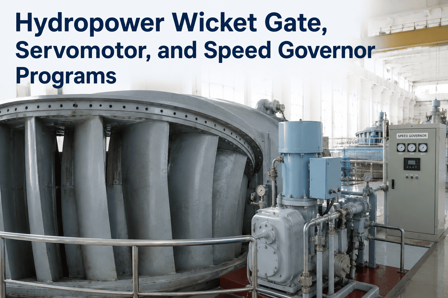
Hydropower Wicket Gate, Servomotor, and Speed Governor Programs
By Johnson on May 25, 2026
The wicket gate, servomotor, and speed governor form the flow-control spine of every hydraulic turbine — three interdependent systems that together determine whether a hydro unit follows load, protects against overspeed, and delivers its rated output across a 40-to-60-year service life. When any of the three degrades, the consequences are not isolated: worn gate bushings cause linkage misalignment that overloads the servomotor; a sluggish servomotor causes the governor to over-correct and hunt; a governor with degraded dead-band causes penstock pressure oscillations that accelerate gate seal wear. These systems fail together, in cascades — which is why the hydropower O&M industry, a market valued at $8.9 billion in 2024 and growing at 5.8% annually, increasingly treats them as a single programme rather than three separate inspection items. OxMaint gives hydropower O&M teams structured PM templates, CMMS-tracked inspection records, and condition-based work order triggers for wicket gate linkage, servomotor hydraulics, and governor response testing — all linked to each unit as a registered asset in one platform. Book a 30-minute walkthrough to see how OxMaint structures hydro governor and gate programmes.
OxMaint · Hydropower Governor & Gate Maintenance
Three Systems. One Cascade. When Gate, Servomotor, or Governor Fails — All Three Pay.
Wicket gates, servomotors, and speed governors degrade together. The plant that maintains them as a system outlasts the one that maintains them as separate work orders.
1.45 TW
Global hydropower installed capacity in 2025
$8.9B
Global hydro O&M market value in 2024
25%
Reduction in unplanned outages with predictive maintenance systems
40–60 yr
Typical hydro unit service life — maintenance is the variable
The Flow-Control Chain: How Wicket Gate, Servomotor, and Governor Work as One System
Understanding why these three components must be maintained together requires understanding how they communicate in real time during every load change the unit makes.
Speed Governor
Senses shaft speed deviation from setpoint. Calculates required gate position change. Commands pilot valve to direct hydraulic oil.
Key components: Speed sensor (PMG), digital PID controller, pilot valve, hydraulic oil supply, position feedback potentiometer
Hydraulic command signal
Servomotor
Receives hydraulic oil from governor pilot valve. Converts hydraulic pressure into mechanical linear or rotary force to move the operating ring and wicket gates.
Key components: Main hydraulic cylinder, piston rod, seals, operating ring linkage pin, position indicator
Mechanical force to operating ring
Wicket Gates
Pivoting aerofoil vanes arranged around the turbine spiral casing. Rotate simultaneously via operating ring and gate arms to control water flow into the runner — and therefore turbine speed and output.
Wicket Gate Maintenance: From Bushing Clearance to Breakaway Pin Verification
What Degrades — and How to Detect It
Bushing Wear
Each gate shaft runs in upper and lower bushings. As clearance grows beyond 0.5–0.8mm, the gate can wobble laterally during operation, causing seal face damage and linkage misalignment. Measured by jacking the gate shaft and measuring movement with dial indicators.
Inspect: Annual | Replace threshold: per OEM clearance specification
Thrust Washer Condition
Thrust washers at each gate arm absorb axial load during gate movement. Worn washers allow axial gate displacement, creating uneven closing forces across the gate set and potential for individual gates to not fully seat on shutdown.
Inspect: Major outage | Replace: at any sign of grooving or cracking
Seal and Seating Surface Wear
Gate sealing surfaces on the facing plates wear from repeated open-close cycles and sand or sediment in the water stream. Loss of sealing increases leakage-past-gate flow, reduces available head during low-gate operation, and creates high-velocity jet erosion on the runner.
Inspect: Annual visual with gates open | Repair: welding and re-machining to drawing dimensions
Breakaway Pin Integrity
Each gate arm incorporates a breakaway pin — a sacrificial element designed to shear before a jammed gate transmits overload force to the operating ring and servomotor. Pins must be matched to OEM shear specification; undersized pins create nuisance trips, oversized pins allow operating ring damage.
Verify: Each major outage | Destructive sample test: per FERC / OEM requirement
Gate Timing: The Hidden Safety Requirement
Wicket gate closing time is not just a performance parameter — it is a safety parameter. Too-fast closure creates water hammer pressure surges that can rupture penstocks. Too-slow closure after load rejection allows overspeed runaway. Gate timing must be verified against design specifications after every significant maintenance activity or servomotor adjustment.
Full Emergency Closure Time
Typically 5–20 seconds — OEM and penstock design specific
Gate Synchrony
All gates must move within 2–3% of each other — measured by individual gate position sensors or stroboscopic inspection
Loss-of-Power Test
Gates must close to safe position on loss of hydraulic oil pressure — spring or accumulator-driven closure verified by timed test per USACE EC 1130-2-216
CMMS Record Requirement
Timed closure results, individual gate positions, and hydraulic pressure during closure — all logged per unit in OxMaint for FERC audit trail
Servomotor Programme
Servomotor Maintenance: Hydraulic Cylinder, Seals, and Oil System Integrity
Hydraulic Oil System — The Servomotor's Life Support
Operating oil temperature range — out-of-range oil degrades seals and viscosity
2,000 hrs
Typical oil change interval — or at any sign of contamination or colour change
Main Cylinder and Piston
Cylinder bore scoring — from contaminated oil or seal failure — allows bypass flow past the piston, reducing servomotor force and response speed. Inspect bore surface on each major outage; score depth greater than 0.3mm requires re-bore or replacement.
Piston Rod Seals
Dynamic seals degrade from pressure cycling, oil contamination, and rod surface roughness. External oil weeping from the rod seal is an early indicator. Replace at any sign of external leakage; record seal type, batch number, and post-installation pressure test in OxMaint.
Oil Pump and Pressure Relief System
Governor oil pumps are typically duplex — one running, one standby. The standby pump must be tested on automatic start every 90 days. Relief valve set pressure must be checked annually against the penstock pressure transient specification; incorrect set pressure contributes to water hammer events.
Accumulator (Pressure Vessel)
The hydraulic accumulator stores energy to operate the gates during oil pump failure or power outage. Bladder condition and pre-charge pressure must be verified annually. Accumulator discharge time — from rated pressure to gate-closed position — is the critical safety test parameter.
Servomotor PM Intervals at a Glance
Quarterly
Standby oil pump auto-start test — record start pressure and run time
Oil temperature check at operating load — flag if above 50°C
Rod seal external leakage inspection — any visible seepage triggers work order
Accumulator pre-charge pressure check — compare vs design pre-charge
Relief valve set pressure verification — adjust if outside ±5% of design
Accumulator discharge test — timed gate closure from accumulator energy only
Piston rod surface inspection — scoring, corrosion, chrome plating condition
Major Outage
Cylinder bore internal inspection — measure taper and out-of-round
Full seal replacement — record new seal specification and batch
Servomotor stroke measurement vs design — compare with historical trend
Piston rod scoring assessment — thermal spray re-coating if needed
Governor Programme
Speed Governor Maintenance: From Dead-Band Calibration to Response Time Testing
01
Speed Sensing — PMG and Sensor
The permanent magnet generator (PMG) or pulse pickup coupled to the turbine shaft produces the frequency signal the governor uses as its speed reference. PMG output voltage must be within specification across the full speed range; a weak or intermittent signal causes governor instability that mimics mechanical problems.
PM: Annual PMG output voltage check at rated speed; inspect coupling and mounting for looseness; clean pickup gap of metallic debris.
02
PID Controller Calibration
The governor's proportional-integral-derivative settings determine how aggressively the gate responds to speed error. Settings that drift from OEM optimum — or that have never been tuned to actual plant hydraulics — cause either unstable hunting (excessive gate movement) or sluggish response (slow load-following). Dead-band calibration defines the minimum speed error that triggers gate movement.
PM: Annual dead-band verification test; step-response test at 5% and 10% load change; record response time and overshoot in OxMaint per unit.
03
Pilot Valve and Distributing Valve
The pilot valve translates the electronic governor command into hydraulic oil flow direction and volume. Wear in the pilot valve spool creates dead-band in the hydraulic response — the gate does not move until the command signal is large enough to overcome the spool's friction, causing the governor to over-command to compensate. This accelerates gate linkage wear significantly.
PM: Annual spool clearance check; pilot valve flow test at rated pressure; replace if flow at standard command deviates more than 10% from baseline.
04
Governor Response Time Testing
Full governor response time — from load rejection event to stable frequency recovery — is the single most important governor performance metric for grid operators. FERC and NERC requirements for frequency regulation participation specify minimum governor response characteristics. Degraded response time (from any component in the chain) can disqualify the unit from frequency regulation revenue.
PM: Semi-annual load rejection test — record peak overspeed, time to 98% speed, gate closure profile; compare vs previous test and OEM specification.
05
Overspeed Protection Systems
The mechanical overspeed trip is independent of the governor — a centrifugal mechanism that triggers gate closure if shaft speed exceeds 130–140% of rated speed. It must be tested at speed under controlled conditions. Failure to test means that in a real load rejection event, an unverified trip mechanism is the last line of defence against runaway and potential structural failure.
PM: Annual overspeed trip test — timed and documented per unit in OxMaint; result logged against previous test for trend tracking.
06
Hydraulic Control Cabinet
Modern electro-hydraulic governors house digital controllers, solenoid valves, pressure transducers, and oil conditioning equipment in a single cabinet. Cabinet internal temperature, filter condition, solenoid response time, and pressure transducer calibration all require structured annual inspection — not just a visual check from outside the cabinet door.
Breakaway pin inspection — dimensional check and sample destructive test
Major outage
Pin dimensions, shear test result, batch number, replacement record
Servomotor
Standby pump auto-start test
Quarterly
Start pressure, run time, pass/fail
Servomotor
Hydraulic oil sample analysis
Annual / 2,000 hrs
Lab report — viscosity, particle count, water content
Servomotor
Accumulator discharge time test — gates to closed on accumulator energy
Annual
Timed discharge, start and end pressure, gate closure confirmation
Servomotor
Rod seal external leakage and cylinder bore inspection
Quarterly visual / Major outage full
Leakage observation, bore measurements at major outage
Governor
Dead-band calibration verification
Annual
Measured dead-band value vs design, date, adjustment if made
Governor
Load rejection and step response test
Semi-annual
Peak speed, recovery time, gate profile — compared vs last test
Governor
Overspeed trip test at speed
Annual
Trip speed, response time, reset verification
Governor
PMG output voltage check and pilot valve flow test
Annual
PMG voltage at rated speed, pilot valve flow rate vs baseline
Frequently Asked Questions
How often should wicket gate bushings be inspected and replaced?
Gate bushing clearance should be measured annually using dial indicators on a jacked gate shaft. The replacement threshold is OEM-specific but typically falls in the 0.5–0.8mm range for total clearance — beyond this, lateral gate movement begins to affect seal integrity and linkage alignment. In units handling high-sediment water, bushing wear rates can be 2–3 times higher than in clean-water plants, requiring more frequent measurement campaigns. OxMaint tracks bushing clearance readings per gate shaft as a time-series record, so deterioration trends are visible across inspection cycles rather than only at point-in-time inspections.
What is the correct hydraulic oil specification for a hydropower governor system?
The oil specification is determined by system operating pressure. At pressures up to 12.5 MPa, L-HL grade hydraulic oil is typically specified; above 12.5 MPa, L-HM anti-wear hydraulic oil is required. Operating temperature must remain within 10–50°C — out-of-range temperatures degrade both oil viscosity and seal compatibility. Oil samples should be analysed annually for viscosity index, particle contamination count (per ISO 4406), and water content, with a full oil change at 2,000 operating hours or on any sample result showing contamination above the specified cleanliness class.
What happens if wicket gate timing is incorrect after a maintenance outage?
Incorrect gate closure time creates two distinct hazard scenarios. Too-fast closure generates water hammer pressure transients in the penstock — documented cases have resulted in penstock rupture or collapse. Too-slow closure after a load rejection allows the unit to accelerate toward mechanical overspeed, risking runner, generator, and bearing damage. Gate timing must be verified against the design closure curve after every servomotor adjustment, seal replacement, or linkage reassembly — and the timed test result recorded in the unit maintenance log. USACE Engineering Circular 1130-2-216 includes specific requirements for gate timing verification and loss-of-power testing.
How does OxMaint support FERC-required maintenance documentation for hydropower units?
OxMaint maintains per-unit maintenance records that include governor response test results, gate timing verification records, overspeed trip test history, hydraulic oil analysis reports, and inspection sign-off documentation — all time-stamped, technician-attributed, and exportable by date range for FERC compliance submissions. Governor dead-band calibration records and load rejection test results are stored against each generating unit as a permanent asset history. Book a walkthrough to see how OxMaint structures hydropower compliance records.
What is a breakaway pin in a wicket gate system and why is it safety-critical?
A breakaway pin — also called a link pin or shear pin — is a sacrificial fastener in each gate arm linkage designed to fail at a specific shear load before a jammed or obstructed gate can transmit overload force to the operating ring, servomotor, or adjacent gates. If a gate strikes debris and cannot move, the pin shears — releasing that gate from the operating ring while all other gates continue to operate normally. Pins must be dimensioned to OEM shear specification — undersized pins cause nuisance trips during normal operation, while oversized pins allow operating ring structural damage when a gate actually jams. Sample destructive testing of breakaway pins on each major outage is standard practice at responsible facilities.
Every Gate Test. Every Oil Sample. Every Governor Response. Tracked in One System, Ready for Any Audit.
OxMaint gives hydropower O&M teams structured PM programmes for wicket gates, servomotors, and speed governors — with per-unit asset records, condition-based work order triggers, and the compliance documentation your FERC inspection team needs without hours of manual compilation.