In March 2025, a 480V main distribution panel at a pharmaceutical packaging plant erupted into an arc flash at 2:17 AM. The blast obliterated the panel, injured a night-shift electrician, and forced a nine-day production shutdown costing $2.1 million in lost output, equipment replacement, and OSHA citations. Post-incident analysis traced the origin to a single loose bus bar connection that had been running 58°C above ambient for months—completely invisible to the naked eye, but screaming for attention on any infrared camera. A $400 thermographic scan during routine maintenance would have flagged this as a "Critical—Immediate Action" finding weeks earlier. This is not an edge case. Electrical failures account for the largest share of industrial fires, and the vast majority originate from thermal conditions fully detectable through infrared thermography long before they become catastrophic.
Oxmaint CMMS transforms thermographic inspection from a one-off contractor report into an automated, repeatable program—scheduling scans by equipment criticality, auto-generating severity-prioritized work orders from IR findings, tracking hot spot progression scan-over-scan, and producing audit-ready NFPA 70B compliance documentation on demand. This guide equips maintenance managers with everything needed to build a world-class electrical thermographic program. Start free trial today.
Predictive Safety Guide 2026
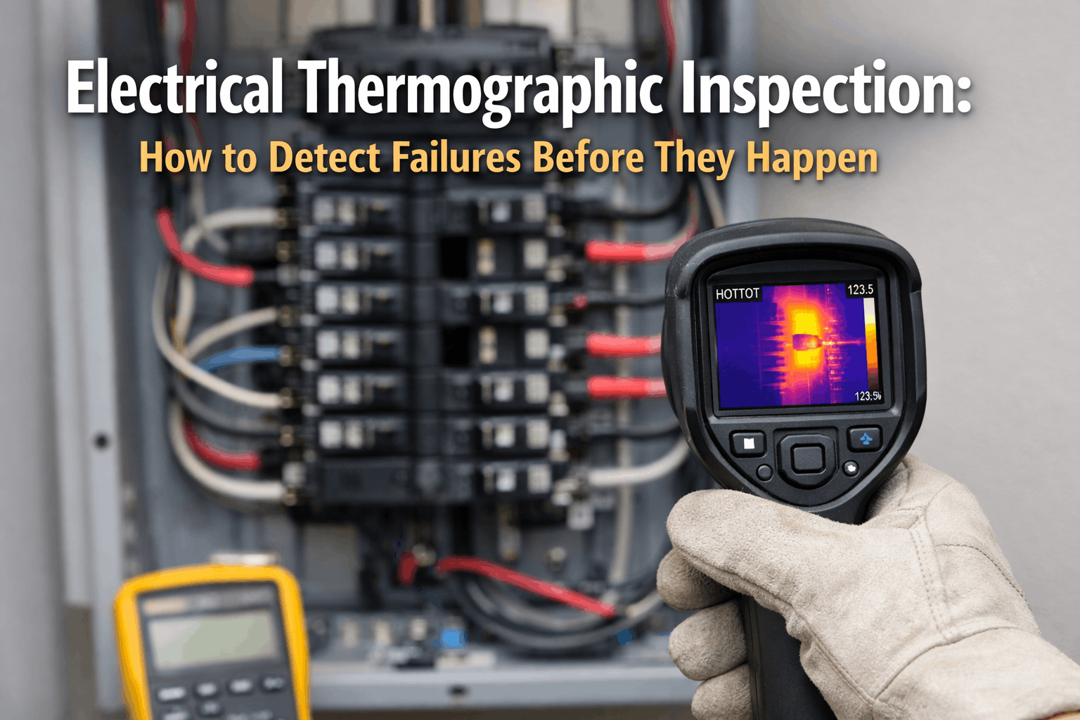
Electrical Thermographic Inspection: Detect Failures Before They Happen
From switchgear bus bars to motor windings, infrared thermography reveals invisible thermal anomalies that precede catastrophic electrical failures. This guide delivers IR scanning procedures, ΔT severity classifications, equipment-specific protocols, and CMMS integration strategies for a zero-arc-flash maintenance program.
70%Electrical Failures Detectable by IR
10:1ROI on Thermographic Programs
$400Avg. Cost per Panel Scan
ZeroArc Flash Target with IR PM
The Thermographic Maturity Spectrum
Most facilities fall into one of three maturity levels for electrical thermographic inspection. While half still rely on "Reactive" approaches—discovering hot spots only after a trip, arc flash, or fire—Oxmaint helps organizations progress toward "Scheduled" and "Predictive" programs where automated CMMS workflows and scan-over-scan trending catch thermal anomalies months before they cause damage. Book a Demo.
Reactive (Post-Failure)
50%
Scheduled (Annual/Semi)
35%
Predictive (CMMS-Driven)
15%
Critical IR Scan Points & Procedures
Every electrical thermographic inspection must follow a systematic approach—scanning specific equipment categories under load, recording baseline temperatures, and comparing against established ΔT (delta temperature) thresholds. A CMMS acts as the central repository for scan results, severity classifications, and the corrective work orders they generate. All scanning must comply with NFPA 70B and NETA MTS requirements for load conditions, emissivity settings, and reporting standards. Book a Demo.
IR Scan Target EquipmentNFPA 70B / NETA MTS
High Voltage
Switchgear & Bus Bars
Scan main bus connections, breaker stabs, fuse clips, and cable terminations through IR viewing ports under minimum 40% rated load. Loose connections generate resistive heating invisible to visual inspection but obvious on thermal imaging.
Arc Flash Risk
Distribution
Panelboards & MCCs
Scan breaker connections, neutral bars, and motor control center buckets. Overloaded circuits and undersized conductors appear as uniform phase heating patterns distinct from single-point connection failures.
Overload Risk
Rotating
Motors & VFDs
Scan motor housings, bearing caps, VFD heat sinks, and cable terminations. Asymmetric bearing heat or hot winding patterns indicate imminent mechanical or electrical failure requiring immediate investigation.
Bearing Failure
Protection
Transformers & Fuses
Scan transformer bushings, cooling fins, tap changers, and fuse holders. Hot fuse clips indicate incipient open-circuit failure; asymmetric transformer heating suggests internal winding insulation breakdown.
Explosion Risk
Connections
Terminations & Splices
Scan all bolted connections, compression lugs, split-bolt splices, and wire nuts in junction boxes. High-resistance connections are the #1 finding in industrial IR surveys—and the #1 ignition source for electrical fires.
Fire Ignition
Utility
Capacitor Banks & Harmonic Filters
Scan capacitor cans for swelling and localized hot spots indicating dielectric breakdown. Check harmonic filter reactor coils for asymmetric heating patterns suggesting component degradation or resonance issues.
Rupture Risk
ΔT Severity Classification Scale
Not all hot spots carry the same urgency. The industry-standard ΔT (delta temperature above ambient or between comparable phases) classification system provides a consistent framework for prioritizing corrective action. This severity scale drives automated work order generation in the CMMS—ensuring critical findings trigger immediate response while minor anomalies are tracked for trending.
4
Critical
ΔT > 40°C above ambient. Major discrepancy. Immediate repair required—failure is imminent. Emergency work order.
3
Serious
ΔT 16–40°C above ambient. Repair at first available opportunity. Schedule within next planned outage window.
2
Intermediate
ΔT 4–15°C above ambient. Warrants investigation. Repair within normal maintenance cycle. Monitor for progression.
1
Minor
ΔT 1–3°C above ambient. Possible deficiency. Log baseline for trending. Rescan at next scheduled interval.
0
Normal
No significant temperature differential detected. Equipment operating within expected thermal envelope. Record baseline.
Automate Your Thermal Inspection Program
Oxmaint transforms IR scan data into actionable maintenance intelligence. Auto-generate severity-prioritized work orders, track hot spot progression over time, and prove compliance with NFPA 70B and insurance requirements—all from a single platform.
Core Thermographic Program Elements
A world-class electrical thermographic program is composed of six interconnected operational modules. Implementing these as digital workflows in Oxmaint ensures scan consistency, proper severity classification, and reliable corrective action tracking from initial finding through verified resolution.
Core
IR Scan Execution
Quarterly / Semi-Annual
Systematic scanning of all energized electrical equipment under load using calibrated IR cameras. Technicians follow standardized scan routes with documented emissivity settings and environmental corrections.
Scan RoutesLoad VerificationEmissivity SettingsImage Capture
Critical
Hot Spot Classification
Per Scan Event
Every thermal anomaly is classified against NETA MTS ΔT severity thresholds. Phase-to-phase and phase-to-ambient comparisons determine urgency level, required response time, and CMMS work order priority.
ΔT MeasurementPhase ComparisonSeverity RatingPhoto Evidence
Integration
CMMS Work Order Generation
Auto-Generated
Each classified finding auto-generates a prioritized work order in Oxmaint with IR image, ΔT reading, asset ID, location coordinates, and recommended corrective action attached for immediate routing.
Auto PriorityIR Image AttachAsset LinkingSLA Tracking
Analysis
Scan-Over-Scan Trending
Every Cycle
Compare thermal images across multiple scan cycles to track hot spot progression. Rising ΔT trends indicate accelerating degradation requiring intervention before the next scheduled scan interval.
Baseline CompareΔT TrendingGrowth RatePredict Failure
Compliance
Reporting & Documentation
Per Cycle
Generate NFPA 70B-compliant reports with thermal images, severity classifications, corrective actions, and verification scans. Satisfy insurance carrier documentation requirements and OSHA recordkeeping.
NFPA 70B ReportInsurance DocsOSHA RecordsAudit Trail
Verification
Post-Repair Validation
After Each Repair
Re-scan repaired equipment under load to confirm the thermal anomaly is resolved. Verification images are linked to the original work order for complete closed-loop documentation and audit evidence.
Re-Scan Under LoadBefore/AfterWO ClosureEngineer Sign-Off
Equipment-Specific Scan Protocols
Different electrical equipment categories present unique thermographic challenges. Switchgear requires scanning through IR viewing ports under specific load conditions, motors need bearing-specific thermal profiles with baseline comparison, and transformers demand bushing-by-bushing analysis. The scan protocol must adapt to each equipment environment while maintaining consistent documentation standards.
Switchgear & Panels
IR viewing ports (closed-door scan)
Minimum 40% rated load required
Phase-to-phase ΔT comparison
Bus bar & breaker stab focus
Cable termination hot spots
Motors & Drives
Bearing cap temperature profiling
Winding hot spot identification
VFD heat sink & capacitor scan
Coupling alignment thermal check
Ventilation blockage detection
Transformers & Utility
Bushing hot spot detection
Cooling fin blockage imaging
Tap changer contact assessment
Capacitor can swelling / heating
Ground connection verification
The Escalating Cost of Undetected Hot Spots
Every catastrophic electrical event—arc flash, fire, or equipment destruction—was preceded by a detectable thermal anomaly that progressed through increasingly urgent severity levels. Each stage represents a missed opportunity where a $400 IR scan could have prevented a multi-million-dollar loss. The "Failure Escalation Pyramid" demonstrates this inescapable progression.
$400
Thermographic Scan
Scheduled IR survey detects ΔT anomaly. Work order generated. Connection re-torqued during planned outage.
Severity 1–2: Monitor / Schedule
$15k–$80k
Component Failure
Undetected hot spot causes breaker trip, conductor meltdown, or contactor welding. Emergency repair plus lost production.
Severity 3: Missed Opportunity
$500k–$5M+
Arc Flash / Fire
Catastrophic arc blast destroys switchgear. Facility shutdown, worker injury risk, OSHA investigation, litigation exposure.
Severity 4: Catastrophic Failure
Stop Hot Spots Before They Become Headlines
Oxmaint provides the digital infrastructure to schedule IR scans, classify findings by severity, auto-generate corrective work orders, and track hot spot trends across your entire electrical distribution system—with full audit trail compliance.
CMMS Features for Thermographic Programs
A purpose-built CMMS is the backbone of any mature thermographic inspection program. It connects IR findings to corrective work orders, ensures nothing is lost between the thermographer's report and the electrician's wrench, and builds the historical baseline data that transforms individual scans into predictive intelligence.
A
Severity-Based Auto Work Orders
Each IR finding classified as Severity 2+ automatically generates a prioritized work order in Oxmaint with the thermal image, ΔT reading, asset ID, location, and recommended corrective action attached for immediate routing to the appropriate technician.
B
Thermal Image Asset Library
Every IR image is stored against its specific asset record—building a historical thermal profile that enables scan-over-scan comparison, ΔT trend analysis, and remaining-life prediction based on degradation rate calculations.
C
Scan Schedule Automation
Auto-generate recurring IR scan work orders by equipment criticality tier—quarterly for switchgear, semi-annually for panelboards, annually for low-risk circuits. No scan cycle is ever missed regardless of staff turnover.
D
Post-Repair Verification Loop
When a corrective work order is completed, Oxmaint automatically schedules a verification re-scan under load to confirm the hot spot is resolved—closing the loop with timestamped before/after thermal evidence.
E
NFPA 70B Compliance Reports
Generate audit-ready reports on demand with scan dates, thermographer credentials, equipment lists, severity findings, corrective actions, and verification records—exactly what insurers, OSHA auditors, and risk managers require.
F
Insurance Premium Documentation
Provide insurers with documented proof of an active thermographic PM program. Many carriers offer 5–15% premium reductions for facilities with CMMS-tracked IR inspection programs demonstrating consistent scan completion and corrective action follow-through.
Frequently Asked Questions
Q. How often should electrical thermographic inspections be performed?
Frequency depends on equipment criticality and operating environment. NFPA 70B recommends annual inspections at minimum for all electrical distribution equipment. Best practice for critical switchgear and motor control centers is quarterly scanning, with semi-annual scans for general panelboards and distribution transformers. High-criticality equipment in continuous-process environments may warrant monthly scans. Oxmaint automates these recurring schedules based on asset criticality tiers so no scan cycle is ever missed.
Q. Does equipment need to be under load during an IR scan?
Yes—this is a critical requirement. Thermal anomalies caused by high-resistance connections and overloaded circuits are only visible when current is flowing through the equipment. NETA MTS standards recommend scanning at a minimum of 40% of rated load. Scanning de-energized or lightly loaded equipment will produce false "clean" results and miss dangerous conditions. Schedule scans during normal production hours when equipment is operating under representative load conditions.
Q. What is the difference between ΔT above ambient and ΔT between phases?
ΔT above ambient compares a component's temperature to the surrounding air temperature—useful for identifying single-point anomalies like a hot fuse clip or loose termination. ΔT between phases compares temperatures across the three phases of the same circuit—a more reliable indicator of connection issues because it eliminates environmental variables. A 15°C difference between Phase A and Phase C on the same breaker is a clear indicator of a high-resistance connection, regardless of ambient conditions. Best practice uses both methods in combination.
Q. Can IR thermography detect problems inside enclosed switchgear?
Yes, when IR viewing ports (windows) are installed. These are permanently mounted, UL-listed crystal or polymer windows that allow infrared energy to pass through while keeping the enclosure sealed and maintaining its arc-flash rating. Technicians scan through the port without opening the door—eliminating arc flash exposure risk entirely. NFPA 70B now recommends IR viewing ports on all medium and high-voltage switchgear. Oxmaint tracks IR port locations and schedules scans per asset automatically.
Q. How does Oxmaint integrate thermographic data into maintenance workflows?
Oxmaint treats each thermographic finding as a structured data event. When a thermographer uploads an IR report, each classified anomaly generates a work order tagged with the asset ID, severity level, ΔT reading, thermal image, and recommended corrective action. The CMMS tracks the work order through assignment, execution, and post-repair verification re-scan—building a complete, auditable lifecycle record for every hot spot from initial detection through verified resolution and baseline reset.