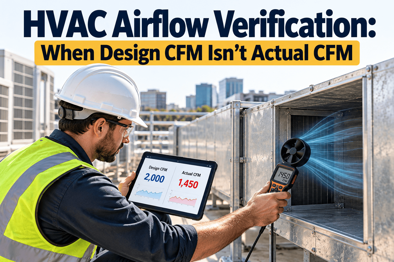
A commercial building can pass commissioning and still deliver the wrong airflow within a few seasons. Design CFM is a calculation made before occupants, tenant fit-outs, dirty filters, and worn dampers exist. Actual CFM is what the fan, ductwork, and terminals deliver today. Closing that gap is the purpose of hvac airflow verification, and it is easier to sustain when test results, corrective work, and re-test dates live in one maintenance management system instead of scattered reports.
When Design CFM Isn't Actual CFM
VAV drift, duct leakage, and coil fouling quietly pull airflow away from design. A repeatable CFM verification test finds the gap before it becomes comfort complaints, wasted fan energy, or a ventilation problem.
Why Design CFM Is Only a Starting Point
- Design values assume clean coils, tight ducts, calibrated controls, and the original space layout.
- Test and balance reports capture airflow on one day, often at commissioning, and age from that point on.
- Tenant changes, added partitions, and relocated diffusers alter airflow paths without touching the design drawings.
- Building automation trends show damper position and setpoints, but not always the airflow physically leaving the box.
What "verification" means in practice
Verification is a measured comparison of delivered airflow against a documented target, using calibrated instruments and a written method. It is different from checking that the controls report the setpoint was met.
- A sensor reading is a signal. A traverse or hood measurement is evidence.
- A passing sensor with a failed measurement usually points to a calibration or installation problem.
The Three Drift Mechanisms That Move CFM
VAV Drift
Variable air volume terminals rely on an airflow pickup, a damper actuator, and a controller that all hold calibration together.
- Actuator wear and linkage slippage change the damper position for the same command.
- Airflow pickup tubes clog or shift, so the measured velocity pressure no longer matches real flow.
- Minimum and maximum setpoints get edited during comfort complaints and never restored.
- Reheat valves and fan-powered boxes add their own failure modes.
Duct Leakage
Air that leaks before the terminal never reaches the occupied space, yet the fan still moves it.
- Loose joints, flexible connections, and access doors leak as buildings vibrate and settle.
- Leakage into ceiling plenums wastes fan energy and can upset space pressure.
- Duct leakage classes and testing methods are defined in SMACNA guidance and referenced by project specifications.
Coil and Filter Fouling
Added resistance forces the fan up its curve, and delivered airflow falls if the system cannot compensate.
- Dirty filters and loaded coils raise static pressure across the air handler.
- Fouled cooling coils reduce heat transfer even when airflow appears acceptable.
- Belt slip, fan wheel buildup, and variable frequency drive limits cap available airflow.
How the Gap Shows Up on the Floor
| Symptom | Likely Airflow Cause | Verification Step |
|---|---|---|
| Zone will not reach cooling setpoint at peak load | Terminal maximum CFM below design, restricted duct, or leakage upstream | Measure terminal airflow at full command with a capture hood or traverse |
| Stuffy or high CO2 space | Minimum airflow or outdoor air fraction below requirement | Verify minimum CFM and outdoor air at the air handler |
| Fan running at high speed with poor delivery | Excess static pressure from filters, coils, or duct restriction | Record static pressure drop across each component |
| Simultaneous heating and cooling complaints | Terminal reheat with drifted airflow pickup or setpoints | Compare controller CFM reading to measured CFM |
| Noise at diffusers | Excess velocity from unbalanced branches | Traverse the branch and compare to balance report values |
The Airflow Verification Test, Step by Step
Pull the baseline
Collect the design schedule, the original test and balance report, and current control setpoints for the system.
Prepare the system
Confirm filters are clean or record their condition, set the air handler to a defined operating point, and note outdoor conditions.
Measure at the source
Traverse main supply, return, and outdoor air where straight duct allows, and record fan speed, motor amps, and static pressure.
Measure at the terminals
Use a flow hood or traverse at each VAV box or a representative sample, at both minimum and maximum commands.
Compare and classify
Calculate variance to design and compare with the tolerance in your specification. Many balance procedures use plus or minus 10 percent, but confirm the project requirement.
Correct and re-test
Repair, recalibrate, or rebalance, then repeat the measurement to prove the fix held.
Instruments and method notes
- Use instruments within their calibration interval and record the calibration date on the test sheet.
- Follow the traverse method named by NEBB or AABC procedures, and note where duct geometry limits accuracy.
- Record test conditions so a later technician can repeat the same measurement fairly.
Prioritizing What to Test First
Design-Only Versus Verified Operations
- Trusts controller readings without field checks
- Investigates airflow only after complaints
- Filter changes follow a calendar, not pressure drop
- Balance report filed and forgotten
- Repairs recorded as a generic hot-cold ticket
- Field measurements compared against a documented target
- Scheduled airflow checks on critical and high-drift assets
- Filter and coil work tied to measured static pressure
- Balance data stored against each terminal asset
- Failures tagged by cause, so repeats become visible
Standards and Reference Points
Keep the contract in view
Your project specification and local code control tolerances and required methods. Treat the figures in this article as general context, and defer to those documents for compliance decisions.
Turning Airflow Verification Into a Maintenance Workflow
What Oxmaint supports in this workflow
- Asset management for the full equipment hierarchy from central plant to terminal unit.
- Preventive maintenance scheduling based on calendar or meter readings.
- Inspection checklists with required measurement fields.
- Work order history that shows repeat failures by asset and cause.
- Inventory tracking for filters, belts, actuators, and pickup tubes.
- Reporting and dashboards for overdue tasks and recurring airflow problems.
Trends Changing How Teams Verify Airflow
- Fault detection tools compare controller data against expected behavior and flag suspect terminals for field checks.
- Permanent airflow measurement stations at air handlers give continuous outdoor air and supply readings.
- Duct static pressure reset strategies depend on accurate terminal feedback, so drifted VAV boxes can undermine the savings.
- Condition-based triggers, such as rising pressure drop across a filter bank, are replacing fixed replacement dates on many sites.
A caution about automated data
Analytics can flag where to look, but a measurement in the field still confirms whether the fault is real. Use software to prioritize testing, not to replace it.
Airflow KPIs Worth Tracking
Field Checklist for Each Test Visit
Common Mistakes That Undermine Airflow Verification
- Testing with dirty filters and treating the result as a permanent baseline.
- Adjusting a terminal without recording the before value, which erases the evidence of drift.
- Using a single sample zone to represent an entire floor of varied loads.
- Correcting airflow at the terminal while an upstream leak keeps stealing supply.
- Failing to update setpoints in the building automation system after a rebalance.