AI Vision Camera Placement · Fleet Yard Design · OxMaint AI
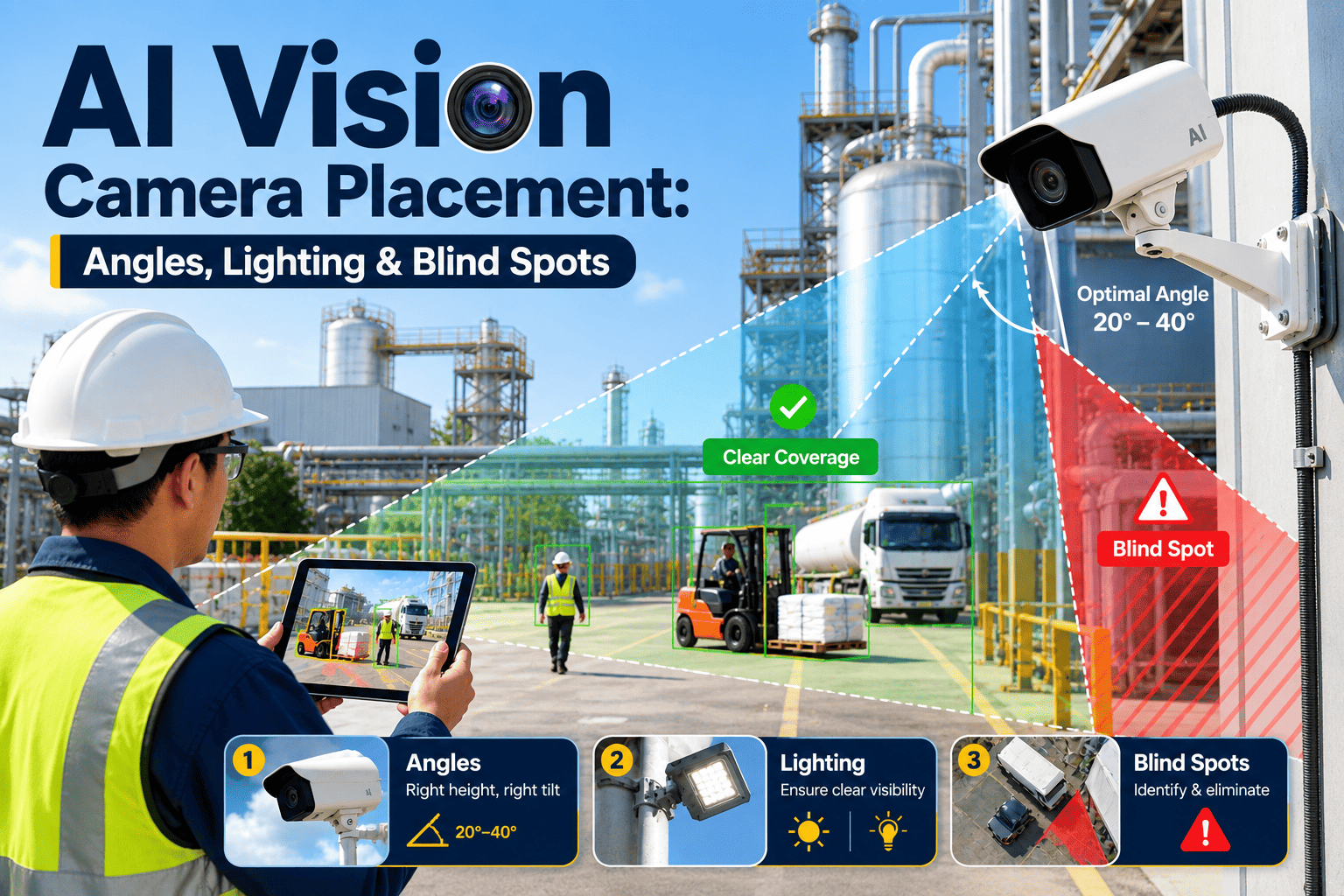
The Angle, The Light, and The Blind Spot Are the Whole Ballgame. Get Camera Placement Right and AI Vision Catches Almost Everything. Get It Wrong and It Catches Almost Nothing.
OxMaint designs AI vision camera layouts for fleet yards and gates — mounting height, approach angle, lighting geometry, and blind spot coverage engineered around how your vehicles actually move through your site, not a generic template.
99%
defect detection accuracy achievable when camera angle, height, and lighting are engineered specifically for the inspection zone
60%
accuracy a well-trained AI model can drop to when cameras are misplaced, poorly angled, or working under uncontrolled ambient light
2mm
smallest surface defect that correctly angled, structured lighting can reveal against a vehicle panel during a drive-through scan
40%
A poorly placed camera array does not just miss a few defects here and there — it can require nearly twice as many cameras to achieve the same coverage a properly engineered layout gets with far fewer units, because overlapping blind spots force operators to add redundant units to compensate. Camera placement planned before installation, with mounting height, tilt angle, and lighting position calculated for each inspection zone, routinely needs 40% fewer cameras than a reactive layout added zone by zone after gaps are discovered. OxMaint plans the full array before the first bracket goes on the wall.
ZONE 1 — Gate Entry & Exit
Entry and Exit Camera Height, Angle, and Approach Distance
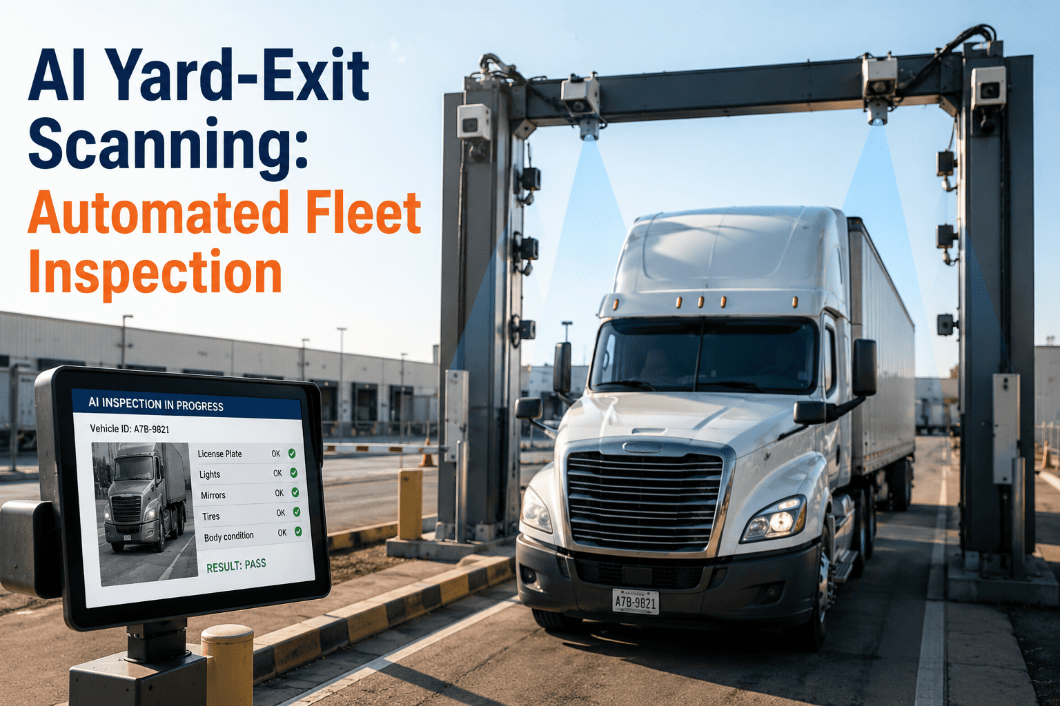
The gate is where most fleets place their first camera and get the geometry wrong. A camera mounted too high looks down at a steep angle and distorts the roofline and upper panels; mounted too low, it misses the undercarriage and reads license plates at an angle that OCR struggles with. OxMaint positions gate cameras at a calibrated height and tilt calculated from your typical vehicle height range, with a second angle dedicated purely to plate and cab identification so the inspection camera never has to compromise on framing to also capture the plate. Approach distance is set so the AI has a full two to three seconds of clean image capture as the vehicle passes through at natural gate speed — no stopping, no dwell time added to the gate.
Mounting height calibrated to fleet vehicle height range, not a fixed default
Separate plate-read angle so identification never compromises panel framing
Approach zone distance set for full capture at normal gate speed
Dedicated night-lane hardware to eliminate headlight glare on plate reads
Placement Mistakes OxMaint Prevents
Single steep-angle camera trying to cover both roofline and plate
Gate camera positioned where headlight glare washes out night captures
ZONE 2 — Lighting Design
Structured Lighting and Ambient Light Control Around the Scan Point
Lighting is the single most underestimated variable in AI vision accuracy. Ambient yard lighting shifts constantly — direct sun at midday, long shadows at dusk, sodium vapor lamps at night — and every shift changes how a panel surface reflects light back to the camera sensor. OxMaint designs the scan zone with structured lighting positioned to overpower ambient variation, using angled strip lighting that creates consistent reflection patterns across every panel regardless of time of day or weather. This is what allows the AI to compare today's scan against yesterday's baseline with confidence, instead of flagging false damage every time the sun moves.
Angled strip lighting positioned to overpower shifting ambient conditions
Consistent light geometry maintained across day, dusk, and night scans
Reflection pattern calibration for dark, light, and metallic paint finishes
Canopy or shade structure recommendation where direct sun hits the scan zone
Placement Mistakes OxMaint Prevents
Ambient light variation causing false-positive damage flags shift to shift
Uncontrolled shadow from overhead structures masking real panel damage
ZONE 3 — Undercarriage & Ground Level
Ground-Level Camera Positioning for Undercarriage and Tire Coverage
Undercarriage inspection is the zone every manual walkaround inspection skips almost entirely, and it is also the zone most fleets place cameras for last, if at all. Ground-level cameras have to survive vehicle weight, road debris, and moisture while still capturing sharp images from a few inches off the ground. OxMaint positions undercarriage arrays in a shallow trench or drive-over housing rated for repeated axle loads, angled to capture frame rails, suspension components, and fluid lines as the vehicle passes overhead, with separate tire-facing cameras on each side to read tread depth and sidewall condition without the driver stopping.
Drive-over housing rated for repeated full-axle load without image drift
Frame rail and fluid line angle calibrated to vehicle ground clearance range
Paired tire-side cameras per side for tread depth and sidewall condition
Debris and moisture housing rated for the yard's actual weather exposure
Placement Mistakes OxMaint Prevents
Ground camera housing not rated for axle load, drifting out of calibration
Single undercarriage camera with no depth to separate overlapping components
ZONE 4 — Blind Spot Coverage
Blind Spot Mapping Across the Full Vehicle Envelope
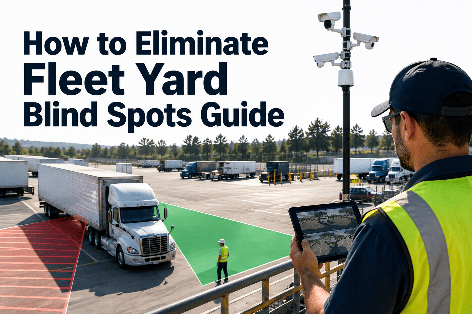
Every camera array has a theoretical coverage map and an actual coverage map, and the gap between them is where damage goes undetected. Wheel wells, the roof center line on tall vehicles, the space between dual trailers, and the underside of mirror housings are the most commonly missed zones because they require an angle no single camera in a standard array can reach. OxMaint builds a coverage map specific to your vehicle mix before installation, identifies every zone no existing camera angle reaches, and adds targeted units only where a genuine gap exists — rather than adding cameras everywhere and hoping overlap closes the gaps by accident.
Vehicle-specific coverage map built before any camera is mounted
Wheel well, roofline, and inter-trailer gap zones identified individually
Targeted camera addition only where a real coverage gap is confirmed
Coverage map re-verified whenever a new vehicle type joins the fleet
Placement Mistakes OxMaint Prevents
Wheel well and mirror housing damage missed by every angle in the array
Coverage map never updated after a new trailer or vehicle type is added
OxMaint AI · Camera Placement Engineering
Right Height. Right Angle. Right Light. Zero Blind Spots. The Difference Between an AI Camera System That Works and One That Just Sits There Recording.
OxMaint plans your full camera layout — gate, undercarriage, tire, and blind spot coverage — before installation, so accuracy is engineered in from day one instead of patched together after gaps show up in the field.
Technology · Lighting AI
Adaptive Lighting Calibration Per Scan Zone
OxMaint continuously measures ambient light at each camera position and adjusts structured lighting intensity in real time, keeping the reflection pattern the AI model was trained on consistent whether the scan happens at noon or midnight, in full sun or driving rain.
Outcome: Same detection accuracy at every hour of the operating day
Technology · Stitching AI
Multi-Angle Image Stitching Into a Single Vehicle Composite
Individual camera feeds from gate, ground-level, and side arrays are stitched into one continuous 360-degree composite per vehicle, so a defect spanning two camera zones — a dent crossing a panel seam, for example — is recognized as one finding, not two partial ones.
Outcome: No defect split, duplicated, or lost at a camera zone boundary
Technology · Coverage AI
Automated Blind Spot Detection Across the Vehicle Envelope
OxMaint runs a coverage simulation against your actual vehicle mix and camera geometry, flagging any surface area no lens angle in the array can reach, then recommends the minimum additional camera count needed to close the gap without over-installing.
Outcome: Coverage gaps identified and closed before go-live, not after a claim
99%
detection accuracy reported by fleets running OxMaint-engineered camera layouts versus generic installation templates
40%
fewer cameras required on average when the layout is planned around real coverage gaps instead of blanket placement
45 sec
average time for a full drive-through scan across gate, undercarriage, and tire zones with no vehicle stop required
Our first camera installer put four units up following a generic layout and told us we were covered. Six weeks in, we had two trailers come back with wheel well damage the system never flagged, because nothing was actually aimed at that angle. OxMaint came in, mapped our actual vehicle mix, and told us we needed two more cameras in completely different spots than the original install, not four more everywhere. Detection accuracy since then has been night and day. It was never the AI that was the problem, it was where the cameras were pointed.
— Yard Operations Manager, Regional Fleet Carrier · OxMaint user since 2023
Frequently Asked Questions — AI Vision Camera Placement
How high should an AI inspection camera be mounted at a fleet gate?
There is no single correct height — it depends on your tallest and shortest vehicle types passing through that gate. OxMaint calculates mounting height from your actual fleet mix rather than a fixed default.
Sign in to OxMaint to review the recommended height for your vehicle range.
Why does lighting matter more than camera resolution for AI accuracy?
A high-resolution camera under inconsistent light still produces inconsistent images, and inconsistent images are what confuse an AI model trained on a stable baseline. Structured, controlled lighting matters more to accuracy than raw camera resolution in almost every yard we have engineered.
Can existing yard cameras be reused in an OxMaint layout?
Often yes, for general yard monitoring positions, but dedicated inspection zones — gate scan, undercarriage, and tire capture — usually need purpose-built placement and lighting that standard security cameras were never designed to provide.
How does OxMaint find blind spots before they cause a missed defect?
OxMaint runs a coverage simulation against your specific vehicle types and proposed camera geometry, flagging any surface area no angle in the array reaches.
Book a demo to see a coverage map built for your yard.
Does camera placement need to change if we add a new vehicle type to the fleet?
Yes. A coverage map built for box trucks will not automatically cover a new tanker or flatbed profile. OxMaint re-verifies the layout whenever a new vehicle type joins the fleet so blind spots do not reappear silently.
The AI Model Was Never the Weak Link. The Camera Angle, the Light, and the Blind Spot Were. Fix the Placement and the Detection Rate Fixes Itself.
OxMaint plans gate, undercarriage, tire, and blind spot camera coverage before a single bracket is installed — so your fleet gets engineered accuracy from the first scan, not a patched-together system discovered gap by gap.