An Energy Recovery Ventilator running at 68% efficiency when it was designed and commissioned for 82% is not a ventilation problem — it is an energy problem, a comfort problem, and a compliance problem waiting for an inspection date. ASHRAE 90.1-2025 has elevated the minimum total energy recovery requirement to 80% for commercial ventilation systems, rendering many under-maintained units non-compliant without a single component failure. Dirty filters are the single most common cause of efficiency loss in ERV and HRV systems: a partially blocked intake filter raises static pressure, reduces airflow, and drops heat recovery effectiveness in a chain reaction that the building automation system never flags because it has no sensors measuring actual core performance. This checklist covers five monitoring zones — filter and core condition, airflow balance and measurement, heat recovery performance, frost control and defrost systems, and controls and documentation — structured to the maintenance intervals that preserve the 80%+ efficiency ASHRAE 90.1 now requires. Book a demo to see how Oxmaint's Energy Optimization feature schedules ERV and HRV maintenance, tracks efficiency readings, and documents ASHRAE 90.1 compliance across your ventilation fleet.
Ventilation Systems · HVAC · Energy Optimization
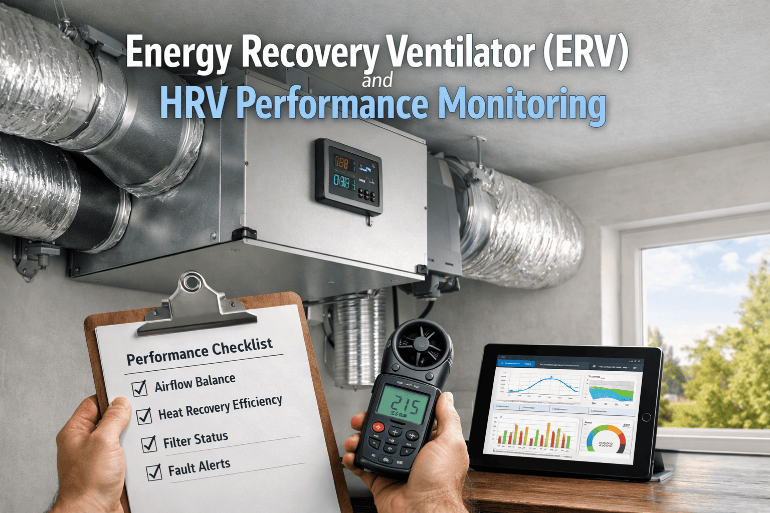
Energy Recovery Ventilator (ERV) and HRV Performance Monitoring
Filter fouling, airflow imbalance, core degradation, and failed frost control are the four failure modes that silently drop ERV and HRV efficiency from design to non-compliant — all detectable with a structured monitoring programme before the next inspection.
80%Minimum total energy recovery required by ASHRAE 90.1-2025 — previously optional in many climate zones
60-95%Actual operating range for ERV/HRV — dirty filters alone can reduce efficiency by 10-15 percentage points
30-50%Heating cost savings vs exhaust-only ventilation from a properly maintained ERV or HRV system
MERV 8-13Filter specification range for ERV/HRV intake — higher MERV increases pressure drop; must match unit capability
HRV vs ERV — What Each System Recovers and How Each Is Maintained
HRV
Heat Recovery Ventilator
Sensible energy only — temperature transfer, no moisture
RecoversHeat (sensible) only
Core materialAluminium or polypropylene plate
Core cleaningWash with mild soap + warm water — dry fully before reinstalling
Frost riskHigh — cores ice up when outdoor temp falls to low 20s°F (-6°C)
Drain panRequired — drain and condensate line susceptible to icing
Best climateCold and dry — removes excess indoor humidity in winter
BypassSummer bypass damper — routes around core during cool nights
ERV
Energy Recovery Ventilator
Total energy — temperature plus moisture (enthalpy) transfer
RecoversHeat + moisture (total enthalpy)
Core materialTreated paper, synthetic membrane, or desiccant-coated
Core cleaningVacuum surface only — DO NOT wash; water damages membrane
Frost riskLower — moisture transfer in gaseous state; frost threshold ~-10°F (-23°C)
Drain panOften not required — ERV avoids condensation in most conditions
Best climateHumid or mixed — manages moisture ingress in summer
BypassSummer bypass less common — latent recovery valuable in humid seasons
Zone 1 — Filters & Core
Zone 2 — Airflow Balance
Zone 3 — Recovery Performance
Zone 4 — Frost Control
Zone 5 — Controls & Records
Zone 01
Filters and Core Condition
Filters are the first line of defence for the heat exchange core and the first component to degrade performance when neglected. A partially blocked intake filter raises system static pressure, reduces supply airflow, lowers heat recovery efficiency, and increases fan energy — simultaneously. The core itself requires inspection and cleaning separately; filters do not protect against fine particulate that bypasses them over time.
Monthly — Filter Inspection
DOE Building America / Manufacturer Spec
Supply air (intake) filter removed and inspected — compare visual soil loading to manufacturer dirty filter reference; a filter at 50% visual blockage is already raising static pressure above design; replace or clean at 3 months maximum regardless of visual appearance
Record: Filter inspection log with replacement date · Role: HVAC Technician
Exhaust air filter inspected — typically captures building particulate before air stream contacts core; high loading on exhaust filter indicates indoor air quality problem (dust, debris, poor housekeeping) worth investigating at source
Record: Filter inspection log · Role: HVAC Technician
Replacement filter MERV rating confirmed against original specification — MERV rating must match unit design; higher MERV improves particle capture but increases pressure drop and reduces airflow; changes to MERV rating require airflow rebalance
Record: Filter specification record · Role: HVAC Technician
Quarterly — Core Inspection and Cleaning
AHRI 1060 / Manufacturer Spec
HRV core removed and cleaned — wash aluminium or polypropylene plate core with mild soap and warm water; rinse thoroughly; allow to dry completely before reinstalling; wet core reinstallation causes moisture issues and early frost events
Record: Core cleaning log · Role: HVAC Technician
ERV core inspected and vacuumed — vacuum dust from surface of paper, membrane, or desiccant-coated enthalpy core only; do not wash ERV paper cores; water contact destroys the moisture-transfer membrane and cannot be remediated
Record: Core inspection log · Role: HVAC Technician
Core frame and seals inspected for cracks, bypass gaps, or compressed gaskets — any gap between core and housing frame allows untreated exhaust air to cross into supply stream (EATR — Exhaust Air Transfer Ratio — increases); document and schedule replacement if core-to-housing seal is compromised
Record: Core condition form · Role: HVAC Technician
Zone 02
Airflow Balance and Measurement
An ERV or HRV that is delivering 60% of design supply airflow because a duct balancing damper was never adjusted at commissioning is performing at 60% of its heat recovery potential regardless of what the core efficiency rating says. Airflow imbalance also creates building pressure problems — excess supply over exhaust pressurises the space; excess exhaust creates negative pressure that forces infiltration and can cause combustion appliance backdraft.
Quarterly — Airflow Verification
ANSI/RESNET/ICC 380-2016 / ASHRAE 62.1
Supply airflow measured using flow hood, flow grid, or pitot tube at each supply terminal — compare to design CFM; total supply airflow should match total exhaust airflow within ±10%; document measurement method and instrument used
Record: Airflow measurement report with instrument calibration reference · Role: HVAC Technician / Commissioning Agent
Exhaust airflow measured at each exhaust terminal — compare to design CFM; document rooms where exhaust is not achieving design rate (typically bathrooms, kitchens, utility areas); duct restriction or hood obstruction is most common cause
Record: Airflow measurement report · Role: HVAC Technician / Commissioning Agent
Fan motor running amps checked against nameplate — rising amps at same CFM indicate partial duct obstruction or filter loading; dropping amps at same speed indicate reduced airflow from duct restriction or closed damper
Record: Electrical log · Role: HVAC Technician
Semi-Annual — Hood and Duct Condition
Manufacturer Spec / Best Practice
Outdoor intake hood and exhaust hood inspected and cleared — leaves, bird nests, lint, and seasonal debris obstruct hood screens; intakes and exhausts must be separated by minimum 10 feet to prevent short-circuiting of exhaust back into supply
Record: Hood inspection form · Role: HVAC Technician
Flexible duct sections inspected for sagging, kinking, or disconnection — kinked or sagging flex duct in supply or exhaust runs dramatically reduces airflow without triggering any alarm; straighten or replace sections with greater than 6-inch sag per foot of run
Record: Duct inspection log · Role: HVAC Technician
Schedule filter changes, track efficiency readings per unit, and document ASHRAE 90.1 compliance — all in one energy optimisation dashboard.
Zone 03
Heat Recovery Performance Verification
Measuring actual heat recovery effectiveness — not just checking that the unit is running — is the only way to confirm ASHRAE 90.1-2025 compliance in operation. A unit rated at 85% effectiveness that is running at 68% due to fouled filters, duct imbalance, or core degradation is non-compliant regardless of its nameplate specification.
Quarterly — Sensible Effectiveness Check
ASHRAE 84 / AHRI 1060
Sensible heat recovery effectiveness calculated from supply and exhaust temperature measurements — record outdoor air temperature (OAT), leaving supply air temperature (SAT), and exhaust air temperature; effectiveness = (SAT - OAT) / (indoor temp - OAT); compare to design value and ASHRAE 90.1 minimum 80% requirement
Record: Performance measurement log with outdoor and indoor conditions at time of test · Role: HVAC Technician / Commissioning Agent
Supply air temperature at each terminal recorded under steady-state conditions — excessively cold supply air in heating season (more than 5°F below design supply temperature) indicates reduced heat recovery effectiveness; first check filter condition and core cleanliness before calling for service
Record: Temperature measurement log · Role: HVAC Technician
Annual — Total Energy Recovery Assessment (ERV only)
ASHRAE 90.1-2025 / AHRI 1060
Total energy (enthalpy) recovery effectiveness verified for ERV units — requires measurement of both dry-bulb temperature and relative humidity at supply and exhaust streams; total effectiveness should meet ASHRAE 90.1-2025 80% minimum; declining enthalpy recovery indicates membrane degradation
Record: Annual ERV performance verification report · Role: Commissioning Agent / HVAC Engineer
EATR (Exhaust Air Transfer Ratio) assessed — any detectable odour from exhaust air in supply stream indicates core bypass leakage; low EATR (near 0%) confirms air stream separation is maintained; a compromised core seal or bypass damper failure allows cross-contamination
Record: Annual performance report · Role: HVAC Engineer / Commissioning Agent
Zone 04
Frost Control and Defrost System Verification
Frost in a heat exchanger core restricts airflow, reduces heat recovery, and — in extreme cases — can physically damage the core. HRV cores are at risk when outdoor temperatures fall to the low 20s°F (-6°C). ERV cores have a much lower frost threshold, typically around -10°F (-23°C), due to moisture being transferred as vapour rather than condensed water. Regardless of unit type, defrost control verification is a seasonal requirement — not an annual one.
Seasonal (Pre-Winter) — Defrost System Check
Manufacturer Spec / ASHRAE 62.1
Defrost control strategy verified before first sub-freezing outdoor temperatures — confirm the installed strategy (exhaust-only cycle, recirculation, preheat coil, or face-and-bypass damper) is operational; test by manually triggering defrost cycle and confirming the correct damper and fan sequence activates
Record: Seasonal defrost verification form · Role: HVAC Technician / Controls Technician
HRV condensate drain and trap verified clear and operational before winter — the condensate drain line is the first point to ice over on HRV units during defrost cycling; a blocked drain causes water to back up into the core housing, accelerating frost formation and potentially freezing the drain pan itself
Record: Seasonal maintenance form · Role: HVAC Technician
Preheat coil (where installed) confirmed operational and temperature setpoint verified — preheat coil heats outdoor air above frost threshold before it contacts the core; failed preheat element on a -20°F design night will result in a frozen core within hours
Record: Preheat coil test record · Role: HVAC Technician / Controls Technician
Monthly (Winter) — Frost Event Monitoring
Manufacturer Spec
BAS/controls defrost cycle frequency reviewed — an increasing defrost cycle frequency over successive cold nights indicates a degraded defrost strategy, a failed preheat element, or indoor humidity conditions approaching the frost threshold; investigate before core damage occurs
Record: BAS alarm and cycle log · Role: Controls Technician / Facility Manager
Supply air temperature drop during defrost cycles confirmed within acceptable range — defrost cycles temporarily reduce or interrupt supply airflow; verify that room temperature recovery after defrost does not create comfort complaints; if defrost cycles exceed 15 minutes or occur more than 6 times per hour, defrost strategy requires adjustment
Record: Defrost cycle log · Role: Controls Technician
Zone 05
Controls, Documentation and Compliance Records
An ERV or HRV without a documented performance verification programme has no defence when an ASHRAE 90.1 compliance review asks whether the 80% energy recovery minimum is being maintained. Controls calibration, scheduled filter replacements, airflow measurements, and seasonal defrost verification all require timestamps and technician identification to constitute a defensible compliance record.
Quarterly — Controls Verification
ASHRAE 90.1 / Manufacturer Spec
Summer bypass damper operation confirmed (where installed) — command bypass open and verify core is fully bypassed; command closed and verify core is re-engaged; a stuck bypass damper left open in winter eliminates heat recovery entirely while appearing operationally normal
Record: Damper functional test log · Role: Controls/HVAC Technician
Occupancy-linked controls verified — where unit is controlled by occupancy sensor or schedule, confirm unit activates at correct occupancy hours and boost mode operates correctly in high-occupancy periods (kitchens, meeting rooms, gymnasiums)
Record: Controls verification log · Role: Controls Technician
Fan speed control (VSD) calibrated and operating correctly — variable speed drives on ERV/HRV fans should modulate to maintain design CFM as filter loading increases; a VSD that maxes out at 100% speed to maintain airflow confirms filter replacement is overdue
Record: Controls verification log · Role: Controls Technician
Annual — Performance Documentation and Compliance Record
ASHRAE 90.1-2025 / AHRI 1060
Annual performance summary compiled — document sensible and total recovery effectiveness measurements, seasonal airflow balance readings, filter replacement dates, and any defrost events for the year; compare against ASHRAE 90.1 80% minimum and manufacturer-rated efficiency
Record: Annual ERV/HRV performance report (retain for building compliance file) · Role: Facility Manager / HVAC Engineer
AHRI certification number verified current for all units — AHRI 1060 certification confirms rated efficiency under standardised test conditions; verify no product recalls or certification changes that affect rated efficiency documentation used for ASHRAE 90.1 compliance claims
Record: AHRI certification record in asset file · Role: Facility Manager
Reference
Monitoring Frequency and Compliance Standards
| Component / Task | Frequency | Key Parameter | Standard |
|---|
| Intake and exhaust filter inspection | Monthly | Visual soil loading; replace at 3 months max | DOE Building America / Manufacturer |
| HRV core cleaning | Quarterly (wash + dry) | Visual condition; no bypass gaps at frame seals | Manufacturer spec / AHRI 1060 |
| ERV core inspection | Quarterly (vacuum only) | Membrane integrity; no water contact | Manufacturer spec / AHRI 1060 |
| Airflow balance measurement | Quarterly; after any filter or core work | Supply = exhaust ±10%; compare to design CFM | ANSI/RESNET/ICC 380-2016 / ASHRAE 62.1 |
| Hood and duct inspection | Semi-annual; after storms | No debris; hoods 10 ft minimum separation | Manufacturer spec |
| Sensible heat recovery effectiveness | Quarterly measurement | Minimum 80% (ASHRAE 90.1-2025 target) | ASHRAE 84 / AHRI 1060 |
| Total energy recovery (ERV units) | Annual verification | Total enthalpy effectiveness at design conditions | ASHRAE 90.1-2025 / AHRI 1060 |
| Defrost control system test | Pre-winter (seasonal) | Correct defrost sequence activates; condensate drain clear | Manufacturer spec / ASHRAE 62.1 |
| Bypass damper function test | Quarterly | Full open and closed stroke achieved on command | Manufacturer spec |
| Annual compliance documentation | Annual | Efficiency measurements vs ASHRAE 90.1 80% minimum | ASHRAE 90.1-2025 / AHRI 1060 |
Expert Review
What Ventilation and Energy Professionals Say
01
The most common ERV performance failure I find during commissioning audits is not a bad core — it is a duct damper that was never set during installation. The unit is running at 60% of design airflow because one branch is wide open and drawing all the flow. After 20 minutes with a flow hood and two damper adjustments, efficiency goes from 68% to 82%. The hardware was fine the whole time.
HVAC Commissioning Engineer, Commercial Ventilation Systems
02
Facilities managers ask me whether they need to track ERV efficiency numbers or just keep a filter replacement log. I tell them: with ASHRAE 90.1-2025 setting an 80% minimum, keeping a filter log is the minimum. Demonstrating compliance requires a dated effectiveness calculation with the outdoor conditions at the time of the test. A filter log is evidence of maintenance. An effectiveness record is evidence of compliance.
Building Energy Code Compliance Consultant, Commercial HVAC
03
An ERV paper core washed with water is a ruined ERV paper core. We see this every year from technicians who cleaned the HRV core last year and did the same thing to the ERV. The enthalpy membrane is a sacrificial component once it contacts liquid water — moisture transfer effectiveness drops to near zero and cannot be restored. Know the core type before touching it.
Senior HVAC Service Technician, Energy Recovery Ventilation Specialist
FAQs
Frequently Asked Questions
How does Oxmaint document ERV efficiency measurements for ASHRAE 90.1 compliance purposes?
Effectiveness measurements are recorded as a custom field on the ERV asset work order, with date, outdoor conditions, and calculated result. Records accumulate in the asset history and can be exported as a compliance report for energy audits.
Book a demo to see the energy performance tracking workflow.
What is the difference between sensible effectiveness and total effectiveness?
Sensible effectiveness measures temperature recovery only — relevant for HRV units and for the heating season performance of ERV units. Total effectiveness (enthalpy) includes both temperature and moisture recovery — the correct metric for ERV ASHRAE 90.1 compliance. ASHRAE 90.1-2025 requires 80% total energy recovery for applicable ventilation systems.
How do I know if my building's ERV or HRV defrost strategy is appropriate for my climate?
Match the strategy to design outdoor temperature. Preheat coil or face-and-bypass damper strategies work best in climates below -10°F. Exhaust-only or recirculation defrost is suitable for moderate climates where sub-freezing conditions are brief. Review the manufacturer's climate zone application guide and verify the installed strategy matches the rated performance at your design outdoor temperature.
How often should HRV and ERV units be professionally recommissioned after initial installation?
Airflow rebalancing is required after any filter or core replacement that could have changed system static pressure, after duct modifications, and annually as a best practice for systems serving multiple zones. ANSI/RESNET/ICC 380-2016 provides the flow measurement procedures; any change greater than 10% from design CFM triggers corrective damper adjustment.
Track ERV and HRV Performance. Document ASHRAE 90.1 Compliance. Automatically.
Oxmaint's Energy Optimization feature schedules filter changes, records effectiveness measurements against the 80% ASHRAE 90.1-2025 requirement, manages seasonal defrost verification, and builds the performance history that turns your ERV and HRV fleet from maintenance obligations into documented energy assets.