HVAC motors, variable frequency drives, and mechanical drive systems represent the highest-concentration maintenance risk in any commercial or industrial facility — they run continuously, they degrade gradually, and they fail suddenly. A 75 kW supply fan motor with uncorrected shaft misalignment loses bearing life at 3–5× the normal rate; a VFD showing harmonic distortion above 5% THD is drawing excess current that shortens both the drive’s capacitor bank and the connected motor’s winding insulation simultaneously. Neither failure announces itself with an alarm until the degradation is already advanced. OxMaint’s Predictive Maintenance AI processes vibration, temperature, current, and power quality data from HVAC motors and drives on a continuous basis — detecting developing fault signatures weeks before threshold alarms activate and auto-generating work orders with the specific fault mode, affected component, and recommended intervention before a trip event forces an unplanned shutdown.
Equipment Reliability · HVAC · Motors, Drives & VFDs
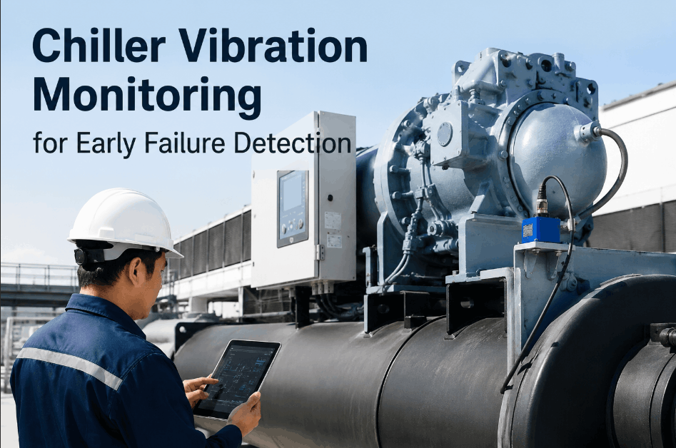
HVAC Motor, Drive & VFD Predictive Inspection System
Vibration, thermal, current signature, and power quality monitoring across HVAC supply fans, exhaust fans, cooling tower motors, chiller drives, and AHU drives — structured for facility engineers, HVAC maintenance technicians, and reliability teams managing critical equipment uptime.
3–5×
Bearing life reduction from uncorrected shaft misalignment in HVAC rotating equipment
70%
of HVAC motor failures are detectable 2–8 weeks in advance through vibration and thermal signature analysis
5% THD
VFD harmonic distortion threshold above which motor winding and capacitor degradation accelerates measurably
$15K–$80K
Cost range per unplanned HVAC motor or drive failure including replacement, labour, and facility downtime
Zone 01 · Pre-Inspection Setup
Pre-Inspection: Asset Documentation & Baseline Review
Predictive inspection without a documented baseline produces readings without context. Before any measurement is taken, establish what the equipment’s normal operating signature is — motor nameplate data, VFD configuration, baseline vibration spectrum, and operating load at time of measurement. Comparison against baseline, not just against generic alarm thresholds, is what differentiates predictive detection from reactive threshold monitoring.
Asset Identity & Nameplate Data
Record motor nameplate data: manufacturer, model, HP/kW rating, voltage, full-load amps (FLA), RPM, efficiency class (IE2/IE3/NEMA Premium), insulation class, and enclosure type (ODP, TEFC, TENV)Record: Asset register entry · Role: Reliability Engineer / Maintenance Technician
Record VFD nameplate and configuration: manufacturer, model, rated output kVA, input/output voltage, firmware version, carrier frequency setting, and motor nameplate data programmed into drive parametersRecord: VFD configuration log · Firmware version noted for manufacturer updates
Retrieve and review prior inspection report for this asset — compare current readings against established baseline spectra, not just against alarm thresholds. A bearing with a 2× baseline vibration increase is significant even if it remains below the generic alarm levelRecord: Prior report reviewed · Baseline spectra compared
Record operating conditions at inspection time: actual load (% of rated), operating speed (Hz or RPM for VFD-driven), ambient temperature, and time since last start — vibration and thermal readings are only comparable across inspections if operating conditions are consistentRecord: Operating conditions at measurement time · Load: ___% · Speed: ___ Hz / RPM
Zone 02 · Motor Mechanical
Motor Mechanical Condition Checklist
Mechanical failure modes — bearing wear, imbalance, and misalignment — account for over 50% of HVAC motor failures. They are also the most detectable: vibration analysis identifies developing bearing faults 4–12 weeks before failure and detects imbalance and misalignment from the first measurement where a baseline deviation appears. Thermal imaging confirms bearing heat generation that precedes vibration-visible degradation.
Monthly — Vibration Route
Quarterly — Thermal + Alignment
Annual — Full Mechanical PM
Monthly Vibration Measurement
Measure overall vibration velocity (in/s or mm/s RMS) at drive end (DE) and non-drive end (NDE) bearing locations, horizontal and vertical axes — record and compare against baseline and ISO 10816 alarm thresholds for equipment classRecord: Vibration reading DE-H, DE-V, NDE-H, NDE-V · Ref: ISO 10816 Class II (<2.8 mm/s = good)
Collect vibration spectrum (FFT) at each measurement point and compare against baseline spectrum — elevated 1× running speed peak indicates imbalance or misalignment; elevated bearing defect frequencies (BPFI, BPFO, BSF, FTF) indicate inner/outer race or rolling element wearRecord: Spectrum data per point · Frequency analysis: Imbalance / Misalignment / Bearing fault / Other
Measure bearing housing temperature at DE and NDE while motor is at operating temperature — bearing temperature >90°C housing or >40°C rise above ambient indicates inadequate lubrication or developing bearing damageRecord: Bearing temp DE: ___°C · NDE: ___°C · Ambient: ___°C · Rise: ___°C
Quarterly Thermal & Alignment
Conduct infrared thermography of motor frame, bearing housings, and terminal box connections — hot spots >10°C above adjacent surfaces indicate localised bearing wear, winding hotspots, or loose electrical connections generating resistance heatRecord: IR image per motor · Hotspot location and ΔT noted · Ref: NETA – >30°C rise = immediate action
Check shaft alignment (laser alignment tool or dial indicator) — angular misalignment >0.5 mrad or parallel offset >0.05 mm for direct-coupled fans and pumps; record values and compare against previous alignment check and coupling manufacturer specificationsRecord: Alignment readings · Angular: ___ mrad · Parallel: ___ mm · Within spec: Yes / No
Inspect motor mounting and baseplate — check for soft foot condition (any motor foot making inconsistent contact with baseplate when fasteners are loosened). Soft foot creates cyclic frame stress that generates false vibration readings and accelerates bearing wear independently of other fault conditionsRecord: Soft foot check · Max foot reading: ___ mm · Acceptable: <0.05 mm
Annual Mechanical PM
Regrease bearings per manufacturer specification — record lubricant type, quantity (grams), and verify grease compatibility with existing lubricant in bearing housing. Over-greasing is as damaging as under-greasing; follow manufacturer-specified volumes, not until grease appears at relief valveRecord: Lubrication log · Lubricant type and quantity · Next interval due
Inspect coupling condition (flexible disc, jaw, or gear coupling) — check for wear, cracking, missing elements, or hardening of elastomeric inserts. Worn coupling elements generate vibration that resembles misalignment and can mask developing bearing issues in spectral analysisRecord: Coupling type and condition · Replace elastomeric elements every 3–5 years regardless of visual condition
Check motor vibration isolation mounts for hardening, cracking, or compression set — failed isolation mounts transmit motor vibration directly to the building structure, increasing occupant noise complaints and falsely elevating structural vibration measurements used for trend comparisonRecord: Isolation mount condition · Deflection: ___ mm · Design deflection: ___ mm
Zone 03 · Motor Electrical
Motor Electrical Condition Checklist
Electrical failure modes — winding insulation degradation, stator turn-to-turn faults, and terminal connection resistance — account for approximately 30–40% of HVAC motor failures. Winding insulation degradation is detectable through insulation resistance testing years before it reaches breakdown voltage; partial discharge activity detectable through motor current signature analysis is the precursor to a turn-to-turn fault event.
Monthly Electrical Checks
Measure and record running current on all three phases (L1, L2, L3) with clamp meter or power analyser — current imbalance >2% between phases indicates voltage imbalance or developing stator fault; sustained overcurrent >105% of FLA indicates mechanical overload or winding degradationRecord: L1: ___ A · L2: ___ A · L3: ___ A · FLA rating: ___ A · Imbalance: ___%
Measure supply voltage on all three phases at the motor starter or VFD output — voltage imbalance >1% at motor terminals accelerates winding heating; a 3.5% voltage imbalance increases winding temperature rise by approximately 25%, significantly reducing insulation lifeRecord: V1: ___ V · V2: ___ V · V3: ___ V · Imbalance: ___% · Ref: NEMA MG1 – max 1% imbalance
Quarterly Insulation Testing
Conduct insulation resistance test (Megger test) at 500V DC for 460V motors: measure IR value at 1 minute (R1) and Polarisation Index (PI = R10/R1) — IR <1 MΩ is critical; PI <1.5 indicates insulation contamination or moisture; PI >4.0 is excellent conditionRecord: IR (1 min): ___ MΩ · IR (10 min): ___ MΩ · PI: ___ · Ref: IEEE 43 · PI <2.0 = investigate
Inspect motor terminal box connections — confirm all terminal connections are torqued to manufacturer specification; photograph any discolouration, pitting, or corrosion on terminals. Loose or corroded terminals generate resistance heat that first appears in IR thermography before producing current imbalanceRecord: Terminal torque check · Discolouration: None / Present (photo taken)
Inspect motor winding temperature via embedded PTC thermistors or PT100 sensors (where present) — confirm alarm setpoints match the motor’s insulation class temperature limit (Class F: 155°C; Class H: 180°C). A motor running at 70% of its insulation class limit has approximately double the winding life of one running at 90%Record: Winding temp reading and insulation class limit · Margin: ___ °C below class limit
Auto-schedule every motor vibration route, IR survey, and Megger test — work orders assigned before the interval expires, not after the trip alarm fires.
Zone 04 · VFD & Drive System
VFD & Variable Speed Drive Inspection Checklist
VFDs are among the most failure-prone components in HVAC mechanical systems despite being designed to extend motor and drive train life. DC bus capacitor degradation, IGBT transistor faults, cooling fan failure, and harmonic-related issues each have distinct signatures detectable before a drive fault event. A VFD that trips and restarts automatically without investigation is masking a developing fault that will eventually become a non-recoverable failure.
Monthly VFD Checks
Review VFD fault log — download or photograph all fault events since last inspection. Every fault event must be investigated: OC (over-current) faults indicate motor or drive overloading; OU (over-voltage) faults indicate DC bus issues or rapid decel; OH (over-heat) faults indicate cooling system failure or ambient temperature exceedanceRecord: Fault log extracted · Fault codes: ___ · Each fault investigated: Yes / No
Confirm VFD internal cooling fan(s) are operational — test fan function with drive de-energised where safe access permits; check for fan noise, reduced airflow, or accumulated dust blockage. Internal cooling fan failure is the most common cause of IGBT and capacitor thermal damage in VFDsRecord: Internal fan status · Fan: Operational / Noisy / Failed · Next replacement due: ___
Measure VFD enclosure internal temperature and ambient temperature at the VFD panel — confirm internal temperature is within drive manufacturer specification (typically <40°C ambient); elevated ambient temperature is the primary cause of premature capacitor and IGBT failure in HVAC electrical roomsRecord: VFD internal temp: ___°C · Ambient: ___°C · Max rated: ___°C
Quarterly Power Quality & Electrical
Measure total harmonic distortion (THD-I) at VFD input — target <5% THD-I for IEEE 519 compliance. Elevated harmonics above 8% accelerate transformer, capacitor bank, and motor winding degradation in the same power distribution circuit. Document measurement location, load level, and instrument usedRecord: THD-I: ___% · Ref: IEEE 519 · >8% = harmonic mitigation required
Inspect DC bus capacitors for visual swelling, leakage, or discolouration — schedule capacitor replacement per manufacturer’s time-based interval (typically 7–10 years regardless of visual condition) or after any sustained over-temperature event. Record installation date of current capacitor bankRecord: Capacitor visual condition · Capacitor installation date: ___ · Next replacement due: ___
Inspect all power and signal cable connections within the VFD enclosure — confirm terminal screws torqued to specification; no loose, discoloured, or overheated connections. VFD terminal connections subjected to vibration from fan or pump vibration transmitted through cable routes loosen progressivelyRecord: Connection torque check · Role: Qualified Electrician
Verify motor protection parameters programmed in VFD are correct: electronic overload set to motor FLA, motor rated voltage, rated frequency, and thermal protection class matching motor nameplate. An incorrectly configured overload setting provides no protectionRecord: VFD motor protection parameters verified against motor nameplate · Correct: Yes / No
Zone 05 · Mechanical Drive Train
Mechanical Drive Train Inspection Checklist
Belt drives, sheaves, and fan shafts are the mechanical intermediaries that transmit motor torque to the HVAC load. They are also the components most frequently inspected but least frequently measured — belt tension checked by feel rather than by tension meter, sheave alignment checked by eye rather than by straight edge or laser. Imprecise drive train maintenance generates the vibration signature that predictive monitoring then identifies as a developing mechanical fault.
Monthly Belt & Sheave Checks
Measure belt tension using a belt tension meter (Hz or force reading) — compare against drive manufacturer tension specification for belt section and span length. Over-tensioned belts load motor and fan bearings with excessive radial force; under-tensioned belts slip and generate heat and vibrationRecord: Belt tension reading: ___ Hz / N · Spec range: ___–___ Hz / N · Within spec: Yes / No
Inspect all belts for cracking, fraying, glazing, oil contamination, or bottom-of-groove wear — glazed belt surfaces indicate belt slip history; oil-contaminated belts must be replaced (oil degrades belt rubber regardless of contamination source)Record: Belt condition · Defect: None / Glazing / Cracking / Oil / Worn · Belt set replacement: Yes / No
Check sheave alignment using straight edge across both sheave faces — parallel misalignment >1.6 mm per metre of span causes edge wear on belts, generates noise, and produces a 2× belt frequency vibration signature detectable in motor vibration spectrumRecord: Sheave alignment: ___ mm per metre · Acceptable: <1.6 mm/m
Quarterly Drive Train PM
Inspect sheave grooves for wear — use sheave groove gauge to measure groove profile. Worn grooves cause belt to ride low in groove, reducing effective drive diameter ratio and increasing slip. Replace sheave set (both sheaves simultaneously) when groove wear exceeds manufacturer toleranceRecord: Groove depth check · Gauge result: Within spec / Worn (replace set)
Verify fan shaft and bearing condition — measure shaft runout with dial indicator (acceptable <0.05 mm TIR for HVAC fans); inspect fan bearing housings for lubricant leakage, overheating discolouration, or cracking. Fan bearing failures are the highest-consequence drive train failure in HVAC — leading to fan wheel contact with housingRecord: Shaft TIR: ___ mm · Fan bearing housing condition: Good / Defect found
Zone 06 · AI Monitoring Setup
Predictive Monitoring Sensor & Platform Configuration
Continuous AI-based predictive monitoring requires correct sensor placement, data transmission configuration, and baseline model initialisation before anomaly detection becomes reliable. A vibration sensor mounted on the wrong axis or a current sensor sampling at too low a frequency provides data that the AI model cannot use to differentiate normal operating variation from a developing fault signature.
Sensor Placement & Commissioning
Confirm vibration sensors are mounted at bearing housings on rigid metal surfaces — sensor must be on load-bearing path, not on housing covers or sheet metal guard panels. Stud-mounting provides the most accurate high-frequency transmission; adhesive mounting acceptable for HVAC motors where stud mounting is impracticalRecord: Sensor mounting method and location per motor · Stud / Adhesive / Magnetic
Confirm sensor sampling rate is adequate for bearing defect frequency detection — HVAC motor bearings require minimum 10 kHz sampling for accurate BPFI/BPFO calculation; general vibration monitoring at 1–2 kHz is insufficient for bearing fault detection in motors above 750 RPMRecord: Sensor sampling rate: ___ Hz · Bearing fault detection capable: Yes / No
Verify OxMaint AI platform is receiving data from all sensors with no transmission gaps — review last 30 days of data continuity per sensor. Any gap >4 hours in a monitored asset is a monitoring failure that must be investigated and resolvedRecord: Data continuity check · Last 30 days gaps: None / Present (sensor or gateway issue)
Baseline Establishment & Alert Configuration
Confirm AI baseline model has been initialised with minimum 30 days of continuous operating data under representative load conditions — anomaly detection based on insufficient baseline produces excessive false positives that reduce team confidence in alerts and lead to alert fatigueRecord: Baseline data period: ___ days · Load conditions during baseline: ___ (normal / atypical)
Configure alert thresholds and routing in OxMaint — vibration anomaly alert at >25% above baseline; thermal anomaly at >10°C above baseline bearing temperature; current imbalance alert at >2%. Alerts must route to a named responsible person with a defined response SLA, not to a generic inboxRecord: Alert thresholds and routing confirmed · Response SLA: ___ hours · Named owner: ___
Confirm AI-generated work orders are being reviewed and actioned — check that the last 3 AI-generated predictive alerts for this asset each resulted in a closed work order with a documented technician finding. Unactioned AI alerts defeat the purpose of predictive monitoringRecord: Last 3 AI alerts reviewed · Each actioned: Yes / No · Technician findings documented
PM KPIs
HVAC Motor & Drive Reliability Metrics
| Metric |
How to Measure |
Target |
OxMaint Tracking |
| Vibration Route Completion Rate |
Monthly routes completed / Scheduled routes |
>95% |
Auto-scheduled per asset; overdue escalation |
| Motor MTBF (Mean Time Between Failures) |
Operating hours / Number of motor failures per asset |
Trending upward quarter-over-quarter |
Failure history per asset; MTBF calculated automatically |
| Predictive Alert Action Rate |
AI alerts actioned within SLA / Total AI alerts generated |
>90% |
Alert-to-work-order closure rate tracked per asset |
| Unplanned Motor / VFD Failure Rate |
Unplanned failures per 100 assets per year |
<5 per 100 assets/year |
Failure classification: planned predictive vs unplanned |
| VFD Fault Event Rate |
VFD fault log events / Operating hours per drive |
Trending toward zero — any recurring fault pattern investigated |
Fault log data per VFD asset; recurring fault pattern flags |
| Insulation Resistance Trend (PI) |
Polarisation Index at each quarterly test per motor |
PI >2.0; downward trend = investigate |
PI trend chart per motor; alert on downward trajectory |
Expert Review
What HVAC Reliability Engineers Say
01
The most expensive HVAC motor failures I investigate are the ones where the vibration data was present in the predictive monitoring system, an alert was generated, and the work order was closed without a technician actually inspecting the asset — because the technician could not find anything wrong on a quick look. Developing bearing faults in the early stage produce vibration at bearing defect frequencies that are not audible and not visible; they require a spectrum analysis. A technician who listens at the motor and hears nothing has not conducted a vibration inspection.
Certified Reliability Engineer (CRE), HVAC Systems Reliability Consultant — 24 Years Rotating Equipment PM
02
VFD capacitor failures are entirely preventable with calendar-based replacement, yet they remain one of the most common causes of drive replacement in commercial HVAC systems. The capacitor bank in a typical 45 kW VFD costs $400–$800 in parts. The drive replacement cost when the capacitors fail and take the IGBT bridge with them is $6,000–$18,000. Every VFD asset record needs an installation date, a capacitor bank age, and a replacement work order scheduled 7–9 years from installation — not from when the first fault event occurs.
HVAC Electrical Engineer, Facilities Management — 400,000 sq ft Commercial Portfolio · 19 Years
03
Shaft alignment is the most under-performed motor PM task in commercial HVAC. Technicians feel that if they can’t hear anything wrong and the belt doesn’t look loose, the alignment must be fine. But a motor with 0.8 mm parallel misalignment generates a radial load on the drive-end bearing that is 6–8 times higher than a correctly aligned motor at the same operating load — visible in the vibration spectrum as an elevated 1× component, invisible to the ear and eye. OxMaint’s predictive alert for elevated 1× running speed is the prompt that gets a laser alignment check completed before the bearing fails.
Vibration Analyst (ISO CAT III), HVAC Mechanical Services Lead · 16 Years Motor & Drive Condition Monitoring
FAQs
Frequently Asked Questions
How often should HVAC motors be included in a vibration monitoring programme?
For critical HVAC motors (supply fans, exhaust fans, cooling tower motors, and chiller compressor drives above 15 kW), monthly vibration measurement routes are the industry standard with continuous online monitoring recommended for motors above 37 kW in critical applications. Motors below 15 kW in non-critical duty can be on quarterly routes. The key principle is that interval determines detection lead time — a monthly route provides a minimum of 4 weeks advance warning of a developing fault; a quarterly route may detect a fault already past the point where intervention is practical.
OxMaint auto-schedules vibration routes by equipment class and criticality rating.
What is the difference between online continuous monitoring and periodic vibration route measurement?
Periodic route measurement involves a technician visiting each asset on a scheduled interval (monthly or quarterly) with a portable vibration analyser, collecting readings, and comparing against baseline. It is cost-effective for large motor populations but provides detection only at the measurement interval. Online continuous monitoring uses permanently installed sensors transmitting data in real time to OxMaint’s AI engine, which detects anomalies as they develop — providing detection in minutes rather than weeks. The appropriate choice depends on asset criticality: continuous monitoring for motors where a failure would cause facility downtime or safety risk; periodic routes for the broader motor population.
Book a demo to see how OxMaint manages both approaches in a single asset dashboard.
When should a VFD be replaced rather than repaired after a fault event?
Replacement is typically more economical than repair when: the drive is >10 years old (capacitor bank and IGBT components approaching end of service life); the drive has experienced multiple fault events in a 12-month period indicating systemic degradation; repair cost exceeds 60% of replacement cost; or the drive model is discontinued with limited spare parts availability. For drives <7 years old with isolated fault events, component-level repair by a qualified service technician is usually economical. OxMaint’s asset record tracks repair cost history per drive, enabling the repair-vs-replace decision with documented cost evidence rather than estimates.
Does OxMaint’s AI require dedicated vibration hardware, or can it work with existing sensor infrastructure?
OxMaint integrates with existing IoT vibration sensors, building automation system (BAS) data points, and SCADA feeds via OPC-UA, MQTT, Modbus TCP, and REST API. For assets without existing sensors, OxMaint works with a range of compatible wireless vibration and temperature sensor options that can be deployed without cable infrastructure. For assets where continuous online monitoring is not warranted, OxMaint also manages periodic route data entered via the mobile app by technicians with portable analysers — combining both data sources in a single asset condition history.
Predictive Maintenance AI · OxMaint · HVAC Reliability
Stop Waiting for HVAC Motor and Drive Trip Alarms. Start Detecting What Causes Them.
OxMaint’s Predictive Maintenance AI connects vibration, thermal, current, and power quality data from every HVAC motor and drive into a single anomaly detection engine — building dynamic baselines per asset, detecting developing faults weeks before threshold alarms, and auto-generating work orders with the fault mode, affected component, and recommended intervention before the trip event forces an unplanned shutdown.