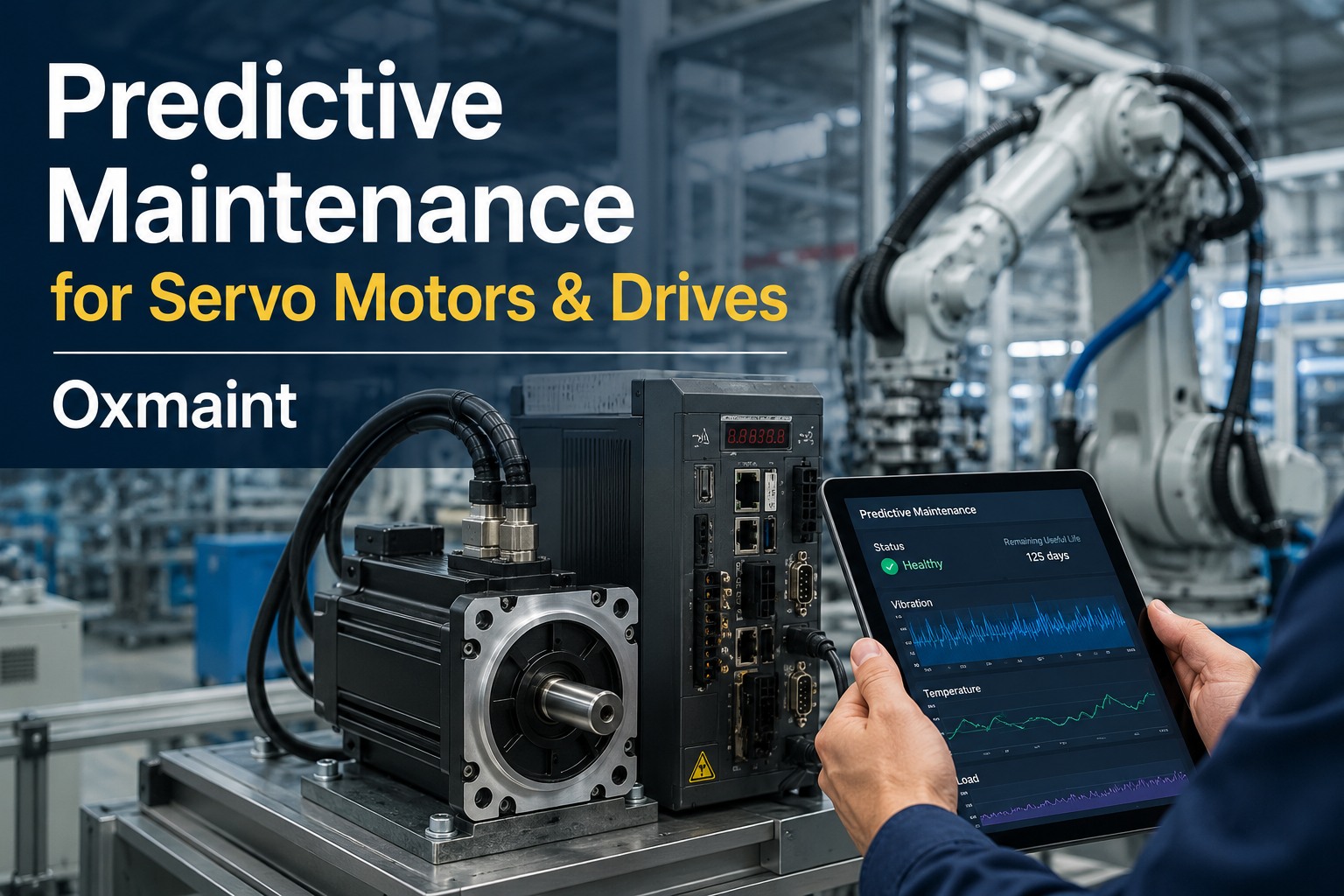
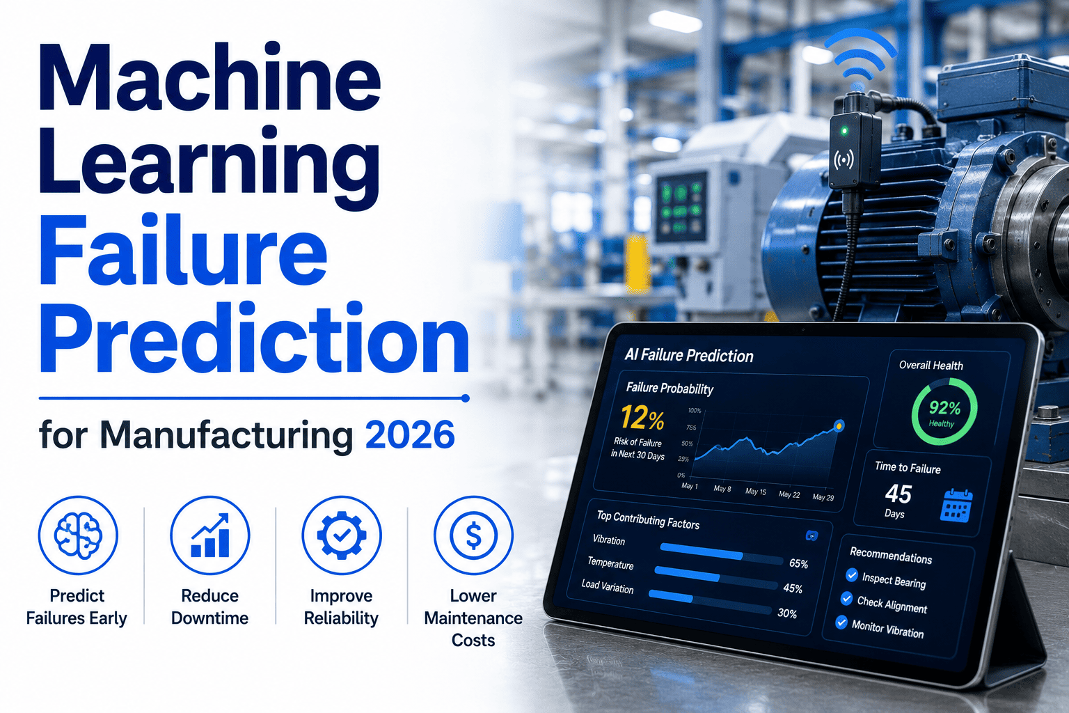
Servo motors don't fail the way standard induction motors fail. In a conventional AC motor, mechanical wear on the bearings and windings is usually the first thing to break — the "muscles" go before anything else. Servos flip that pattern. Because a servo is a closed-loop precision system with an encoder, a dedicated drive, and PWM switching in the kilohertz range, its brain (the encoder feedback) and its nervous system (the drive-to-motor cabling, insulation, and control logic) very often fail before the muscles show any traditional distress signal. A microsecond of encoder signal attenuation can throw a ghost fault or trip the drive without warning. PWM-induced shaft voltages carve fluting into bearings that no calendar-based PM would ever catch. Winding insulation degrades from rapid dv/dt spikes years before it would degrade under sinusoidal supply. All of which means: standard motor predictive maintenance approaches under-detect servo failure. What works instead is a purpose-built multimodal pipeline that fuses vibration, current signature, encoder residuals, thermal, and drive fault logs into a single failure-mode-aware model — and pushes the resulting intervention into the CMMS work order queue before the drive trips a line. This guide walks the servo-specific failure landscape, the sensor signals that catch each mode early, and the AI predictive workflow that turns them into scheduled action. Book a free demo on your servo landscape.
4–8 wk
Lead time typical for servo joint failure prediction with multimodal sensor fusion
70–80%
ML model accuracy on harmonic reducer, encoder, and bearing fatigue prediction
20–25%
Reduction in robot-related path excursions and unscheduled servo replacement
Up to 80%
Motor downtime reduction reported with AI-powered early failure detection
Why Servos Fail Differently · The Brain-Before-Muscle Pattern
Understanding servo failure demands letting go of the standard motor mental model. A servo is not a spinning shaft with copper windings — it's a tightly coupled electromechanical system where the encoder feedback loop, the drive electronics, the PWM switching, and the mechanical rotor all interact. Failure in any one of them cascades into the others in microseconds. The four dominant servo-specific failure paths are almost invisible to conventional monitoring.
Mode A
Encoder Feedback Degradation
Signature: Position error spikes · quadrature signal amplitude drop · rising residuals
Optical or magnetic encoder scale contamination, LED aging, or read-head misalignment corrupts feedback. Drive sees ghost jitter, closes loop tighter, current draw spikes. First warning weeks before drive trips.
Mode B
PWM-Induced Bearing Fluting
Signature: Bearing defect frequencies with EDM-signature pit patterns · shaft voltage spikes
High dv/dt from PWM switching couples through parasitic capacitance to the rotor. Circulating currents arc across bearing races, creating fluting or frosting. Invisible to standard vibration until the pit pattern degrades to full BPFO.
Mode C
Winding Insulation dv/dt Breakdown
Signature: Partial discharge · current asymmetry · rising ground leakage · insulation resistance decline
Rapid voltage spikes from IGBT switching stress winding insulation far beyond sinusoidal-supply expectations. Long motor cables amplify the effect. Turn-to-turn shorts develop months before ground fault trips the drive.
Mode D
Harmonic Reducer & Gear Wear
Signature: Torque ripple growth · backlash increase · position settling time drift
Strain-wave (harmonic) reducers and planetary gearboxes on robot joints wear progressively. Torque signature widens, backlash lengthens the settling time on high-precision moves. Path accuracy degrades before an audible symptom appears.
The Multimodal Sensor Stack · Why One Signal Isn't Enough
Because servo failures cascade across electrical and mechanical domains, single-modality monitoring misses most of them. Vibration alone won't catch encoder degradation. Current alone won't catch mechanical backlash. Thermal alone won't catch PWM bearing fluting. A working servo PdM program fuses five complementary signal streams — each catches a different failure phase, and together they trigger interventions weeks before failure.
Signal Stream
What It Catches Early
Sample Rate
Where It Fails Alone
Vibration (accelerometer)
Bearing defects · unbalance · misalignment · looseness
10–25 kHz FFT
Blind to encoder faults, PWM fluting until late-stage
Motor current signature (MCSA)
Rotor bar defects · winding asymmetry · load anomalies
Sub-second per phase
Weak on mechanical looseness · misalignment
Encoder position error / residuals
Encoder scale contamination · read-head misalignment · quadrature drift
Servo loop rate (kHz)
Cannot see winding or bearing issues
Torque signature / current ripple
Gear backlash · reducer wear · load coupling degradation
Servo loop rate
Weak on winding insulation or electrical faults
Thermal (IR / RTD / drive logs)
Cooling failure · overload · winding hotspots · IGBT thermal margin
Seconds to minutes
Lags most fault modes · symptom of late-stage degradation
The Bearing Fluting Problem · A Servo-Specific Failure Mode
Bearing fluting deserves its own section because it is the single most common servo-specific failure mode invisible to standard monitoring and it is entirely a byproduct of drive electronics. Understanding it changes how you monitor and how you specify the drive-motor-cable system.
1
High dv/dt at IGBT
Servo drive IGBT switches at 4–16 kHz with rise times as fast as 50 nanoseconds — dv/dt exceeds 5 kV/µs on modern SiC drives
→
2
Common Mode Voltage on Shaft
Parasitic capacitance couples common-mode voltage from stator windings onto the rotor · shaft voltage rises above bearing insulation threshold
→
3
EDM-Style Arcing Across Bearing
When shaft voltage exceeds lubricant dielectric strength (roughly 5–30 V depending on load), current arcs across the bearing races — mini electrical-discharge-machining events
→
4
Fluting · Frosting · Failure
Micro-pits accumulate into visible fluting patterns · vibration signature at BPFO / BPFI emerges · bearing seizure follows weeks to months later
What Catches It Early
Shaft voltage probe measuring peak-to-peak · high-frequency envelope demodulation on vibration signal · early detection of EDM-signature pit spectrum. Mitigations: insulated bearings on non-drive end, shaft grounding rings, dv/dt filters, common-mode chokes.
The Servo Predictive Workflow · Signal to Work Order
Once the sensor stack is in place, the workflow that turns those signals into scheduled action is the same six-stage pipeline that governs any predictive maintenance program — but tuned for the fusion patterns unique to servo systems. Each stage has servo-specific configuration that separates a working program from a dashboard-that-nobody-acts-on.
01
Signal Ingest at Native Rate
Accelerometer at 25 kHz · MCSA at sub-second · encoder residuals at servo loop rate · torque signature from drive · thermal from IR or drive registers · drive fault logs via EtherCAT / Profinet
02
Edge Feature Extraction
FFT / envelope on vibration · MCSA sideband detection · position error statistics · torque ripple RMS · thermal delta from baseline · features published every 60 seconds via MQTT Sparkplug B
03
Multimodal Fusion & ML Inference
Trained models cross-reference vibration, current, encoder, torque, thermal signatures · fault classification specific to servo modes (encoder, fluting, insulation, gear) · RUL estimate per identified mode · confidence scoring
04
FMEA-Linked Work Order Creation
Predicted mode maps to matching FMEA entry · work order auto-generated with fault type, RUL, sensor evidence attachments, parts reservation (encoder assembly, bearing kit, insulation test kit)
05
Technician Mobile Execution
WO delivered to phone within minutes · spectral plot, encoder waveform, thermal history attached · procedure pulled from asset record · offline sync for plant dead zones
06
Closeout · Model Feedback
Findings on the failed component push back into ML training set · predicted RUL validated against actual failure timing · fault classification tuned for the specific servo model and duty cycle
See the Servo Pipeline on Your Actual Assets
30-minute technical walkthrough — bring your servo drive brand, motor model, and encoder type. We'll show the multimodal fusion pipeline running against your specific hardware, with FMEA-linked WO creation into your CMMS.
Where Servos Live · And Why the Payback Is Big
Servos live at the highest-leverage points in a modern manufacturing plant — the assets where downtime cost per hour is highest and where failure cascades across a whole line. The archetypes below share a pattern: the servo is not a supporting player, it's the constraint. RCM investment on servo predictive maintenance pays back faster than almost any other class of asset investment.
Robotics
Six-Axis Assembly & Weld Robots
4–6 joint servos per robot · precision reducers · path-accuracy critical · a single joint fault scraps WIP and damages downstream tooling
CNC
Machining Centers & Multi-Axis Mills
Spindle plus 3–5 axis servos · tight positional tolerance · encoder degradation ruins surface finish long before a fault code
Packaging
High-Speed Fillers, Cappers, Labellers
Multiple synchronized servos on cam profiles · registration drift means product rejection · downtime scales with SKU throughput
Print
Flexo, Gravure & Digital Web Presses
Servo-driven color registration · tension control across web · one servo drift kills entire print run and web material
Textile
Weaving, Knitting, Spinning Servo Trains
Dozens of synchronized servos per loom · warp/weft coordination · a single failure stops the machine and produces defect-laden fabric
Semi
Wafer Handlers & Lithography Stages
Nano-precision servos · cleanroom operation · unplanned downtime hourly cost among the highest of any manufacturing sector
Expert Perspective · Why Standard Motor PdM Under-Detects Servos
Every reliability team we work with has the same story about servos. They deployed a motor predictive program using vibration analysis, thermal, maybe motor current signature analysis — the standard three-legged stool for induction motors. It worked well on the pumps, fans, compressors, standard AC motors. But servos kept failing without warning. Ghost drive trips, position errors mid-cycle, encoder faults, bearing seizures out of nowhere. Reliability engineers looked at their vibration data after each failure and the signature was clean until a day or two before, sometimes hours. What was actually happening is that the encoder had been degrading for weeks, the drive was compensating by driving harder, current draw was climbing, and the mechanical signature only shifted at the very end of the failure chain. Standard motor PdM was reading late-stage muscles when the brain had been sick for a month. The fix is not to add more vibration monitoring. It's to add the four signals that catch servo-specific modes — encoder residuals, drive fault logs, torque signature, shaft voltage — and fuse them at the model layer with the vibration and current data. When you do that, the same servos start showing 4–8 week prediction lead times. Path excursions drop 20–25% because you're catching harmonic reducer wear before it degrades cycle accuracy. That's what a servo-specific predictive program looks like, and it's why generic motor PdM tools fall short on the assets that matter most in modern plants.
Brain Fails Before Muscle
Encoder and drive electronics degrade weeks before vibration signature shifts. Monitor feedback loop signals or you'll always be late.
Fluting Is a Drive Problem
PWM bearing damage is caused by drive electronics, not mechanical wear. Standard vibration only catches it after the pits are through the hardened surface.
Fusion Beats Single Modality
Five signal streams together detect all four servo failure modes. Any one alone catches maybe two. Multimodal fusion is not optional for servos.
How OxMaint Delivers Servo-Native Predictive Maintenance
OxMaint is architected for multimodal PdM from day one, with servo-specific fault libraries and model tuning that generic CMMS platforms don't include. Every capability below is native to the platform — no separate motor analytics vendor, no bolt-on module, no systems integrator.
Ingest
Multimodal Servo Signal Stack
Vibration · MCSA · encoder residuals · torque signature · thermal · drive fault logs — all five signal streams unified per servo asset
Analyze
Servo-Specific Fault Library
Trained on encoder degradation, PWM fluting, dv/dt insulation breakdown, harmonic reducer wear — not just generic bearing/winding models
Predict
Fusion-Based RUL Estimation
Cross-signal correlation drives 4–8 week lead times · fault classification narrows to the specific failed component · confidence-scored predictions
Route
FMEA-Linked Work Order Fire
Predicted mode auto-matches FMEA entry · WO created with fault type, RUL, sensor evidence, parts reservation, procedure attachment
Execute
Mobile Technician Delivery
Servo WO on phone with spectral plot, encoder waveform, drive fault log · procedure pulled from asset record · offline sync support
Learn
Closed-Loop Model Refinement
Closeout data feeds back into training pipeline · model tuned per servo model and duty cycle · prediction accuracy compounds over months
Catch Servo Failures Weeks Before the Drive Trips
Stop letting generic motor PdM miss the failure modes unique to servos. See how OxMaint's multimodal fusion pipeline detects encoder degradation, PWM fluting, insulation breakdown, and reducer wear early — with FMEA-linked work order creation into your CMMS. Free forever plan available.
Frequently Asked Questions
Why doesn't standard motor predictive maintenance work well on servo motors?
Because servos fail differently than standard induction motors. In a servo system, the encoder feedback loop, the drive electronics, and PWM switching interact in ways that create failure modes invisible to vibration and thermal monitoring alone. The encoder can degrade for weeks — quadrature signal drift, scale contamination, read-head misalignment — before any mechanical symptom appears. PWM switching at kilohertz rates induces shaft voltages that cause bearing fluting, again with no vibration signature until late-stage. Winding insulation breaks down from rapid dv/dt spikes that don't exist under sinusoidal supply. A working servo PdM program needs five signal streams — vibration, motor current, encoder residuals, torque signature, thermal — fused into a servo-specific model library, not the generic three-signal induction motor toolkit.
What is PWM-induced bearing fluting and why should I care?
Servo drive IGBTs switch at 4–16 kHz with rise times as fast as 50 nanoseconds — modern SiC drives exceed 5 kV/µs dv/dt. This common-mode voltage couples through parasitic capacitance to the rotor shaft. When shaft voltage exceeds the dielectric strength of the bearing lubricant (typically 5–30 V), current arcs across the bearing races in mini electrical-discharge-machining events. Over weeks to months these pits accumulate into fluting patterns visible only late-stage on vibration monitoring, at which point bearing seizure is often imminent. Early detection requires shaft voltage measurement or high-frequency vibration envelope demodulation. Mitigation includes insulated non-drive-end bearings, shaft grounding rings, dv/dt filters, and common-mode chokes.
Book a free demo to see fluting detection.
What sensors do I need on each servo to start predictive maintenance?
A working multimodal setup uses: a tri-axial accelerometer on the motor housing (typically 10–25 kHz for FFT), motor current sampled per phase (sub-second sampling for MCSA), encoder position error/residuals streamed from the drive at servo loop rate, torque signature or current ripple from the drive, and thermal input from IR sensors on the housing or drive-register temperature reads. Drive fault logs pulled via EtherCAT or Profinet round out the picture. Most modern servo drives expose the electrical and encoder data through their fieldbus already — often only the accelerometer needs to be added as external hardware. Start narrow: instrument the top 5 constraint-servo assets first, prove the workflow, then scale.
How much prediction lead time can I realistically expect on servo failures?
With full multimodal sensor fusion, prediction lead times of 4–8 weeks are typical for harmonic reducer wear, encoder degradation, and joint bearing fatigue. Reported ML model accuracy on these modes runs 70–80% for well-tuned platforms with sufficient training data. Automotive plants running these programs report 20–25% reductions in robot-related path excursions and unscheduled joint replacements. Overall motor downtime reductions of up to 80% are reported for facilities that fully deploy the workflow across their constraint-servo assets.
Sign up free to model your specific lead times.
Does OxMaint integrate with our specific servo drive brand (Rockwell, Siemens, Yaskawa, Fanuc, Beckhoff)?
Yes — OxMaint's ingest layer supports OPC UA, MQTT Sparkplug B, Modbus TCP/RTU, Profinet, EtherCAT, and REST, which covers the fieldbus interfaces of every major servo drive vendor including Rockwell Kinetix, Siemens SINAMICS, Yaskawa Sigma-7, Fanuc, Mitsubishi MELSERVO, Beckhoff AX, and Bosch Rexroth IndraDrive. Drive fault logs, encoder residuals, torque signature, and MCSA data stream in via the drive's native fieldbus rather than through separate hardware. External accelerometers add high-frequency vibration data. The multimodal signals unify at the platform layer regardless of drive vendor.
How do OxMaint's predicted work orders integrate with our existing CMMS or SAP PM?
OxMaint pushes predicted work orders into your existing CMMS or SAP PM via standard interfaces — BAPI, RFC, OData V4, or REST — with no ABAP customization or Basis transport changes required. The predicted WO includes servo asset ID, fault type classification, RUL estimate, sensor evidence attachments (spectral plots, encoder waveforms, thermal history), parts reservation, and recommended procedure. Technicians see it on their phone the same way they see any other work order. Closeout data flows back into OxMaint's model training loop so predictions get better over time. The free forever plan is available to trial the workflow end-to-end.
Book a free demo to test the CMMS integration.