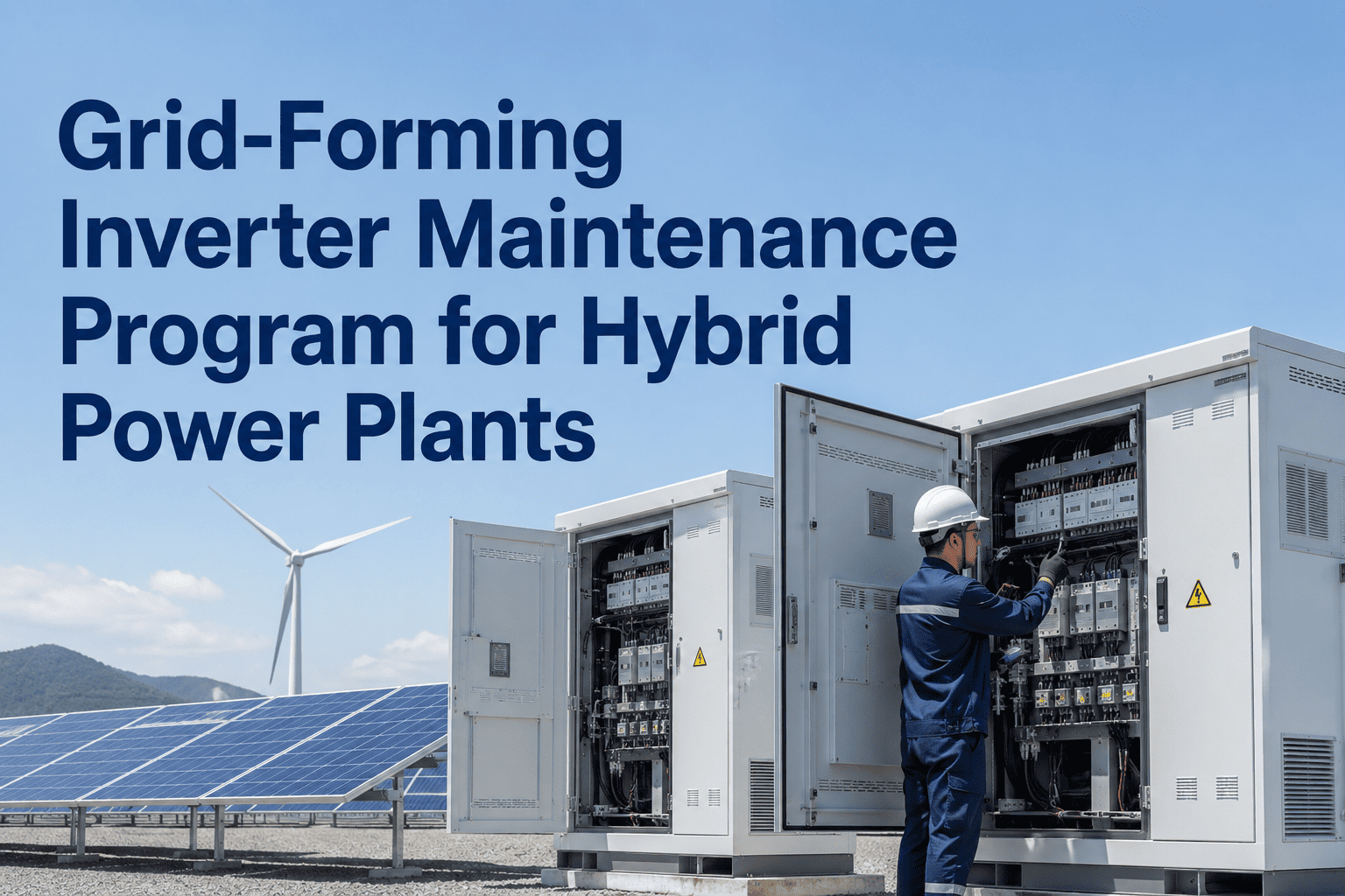
Grid-forming inverters represent a fundamental shift in how renewable generation plants interact with the power system — and the maintenance programs that worked perfectly well for grid-following inverters in a conventional grid are structurally inadequate for grid-forming technology. A grid-forming inverter actively synthesizes voltage and frequency references rather than synchronizing to an externally provided grid signal, which means its internal control loops, power electronics thermal management, and DC link conditioning all operate under fundamentally different stress profiles than their predecessors. When these inverters fail or degrade, the consequences extend beyond the individual plant — a grid-forming inverter plant that loses its voltage synthesis function can destabilize a portion of the grid that was relying on it for frequency support. This article covers the specific maintenance program elements that grid-forming inverter technology requires, the failure modes that differ most significantly from grid-following inverters, and how a preventive maintenance schedule integrated with a CMMS ensures that control system firmware, thermal management, and power electronics components are maintained to the specifications that grid-forming performance depends on. Sign up for Oxmaint to build your grid-forming inverter PM program, or book a technical consultation with our renewable reliability team.
How Grid-Forming Inverters Differ From Grid-Following — And Why It Changes Maintenance
Characteristic
Grid-Following Inverter
Grid-Forming Inverter
Voltage Reference Source
External — locks to grid voltage via PLL
Internal — synthesizes voltage reference autonomously
Frequency Response
Passive — no inherent frequency response without droop control add-on
Active — provides inertia emulation and immediate frequency response
Black Start Capability
Cannot energize a dead grid — requires live voltage reference
Can energize a de-energized grid segment from cold start
Control Loop Complexity
Moderate — current control loop primary
High — voltage control outer loop plus current inner loop with virtual impedance
Firmware Sensitivity
Moderate — firmware updates affect power quality parameters
High — firmware updates affect stability behavior and grid support functions simultaneously
Thermal Management Demand
Proportional to output power level
Elevated during reactive power provision and fault ride-through even at low active power
Maintenance Consequence of Failure
Loss of generation from one inverter
Loss of grid support function — potential grid stability impact beyond the plant boundary
Grid-Forming Inverter Failure Modes — What Maintenance Programs Must Target
Critical
DC Link Capacitor Degradation
DC link electrolytic capacitors in grid-forming inverters experience accelerated aging under the reactive power cycling demanded by grid support functions. Capacitance loss below 80% of rated value causes DC voltage ripple that destabilizes the inner control loop, producing oscillatory behavior before eventual trip. Capacitor equivalent series resistance (ESR) measurement during scheduled maintenance is the primary early detection method.
PM Interval: ESR measurement every 12 months; visual inspection every 6 months
Critical
Control Board Component Drift
Precision voltage and current sensing components on the control PCB — current transformers, voltage dividers, ADC reference circuits — are subject to thermal-mechanical stress from the elevated temperatures in the converter enclosure. Component drift of 2 to 3% in these sensing circuits causes the voltage regulation error to exceed grid code voltage accuracy requirements, triggering regulatory non-compliance before any physical failure occurs.
PM Interval: Calibration verification against calibrated reference every 18 months
High
IGBT Gate Drive Circuit Degradation
The gate drive circuits that switch the IGBT power semiconductors in grid-forming inverters operate under more demanding switching duty cycles than equivalent grid-following designs because the voltage synthesis function requires tighter switching timing. Gate drive circuit degradation produces increased switching loss, thermal stress on IGBT junction, and eventually short-circuit events at the most stressed switch positions in the phase legs.
PM Interval: Switching waveform analysis every 12 months; gate resistance check every 6 months
High
Cooling System Flow Restriction
Liquid-cooled grid-forming inverters serving reactive power support functions generate heat loads at low active power output — a condition that is unusual for liquid cooling system design that assumes full load as the worst case. Deionized water conductivity rise, coolant flow restriction from biofouling or scaling, and pump bearing wear all reduce the cooling margin precisely when the inverter is operating in reactive compensation mode under grid stress events.
PM Interval: Coolant conductivity and pH check monthly; flow rate verification quarterly
High
Firmware Version Drift and Incompatibility
Grid-forming inverters in a multi-inverter plant must operate at compatible firmware versions — or at minimum, compatible control parameter sets — to prevent oscillatory interaction between inverters whose virtual impedance settings do not match. Ad hoc firmware updates applied to individual inverters without fleet-level validation have caused real-world grid-forming plant instability events. Fleet firmware management must be a formal maintenance activity, not an opportunistic one.
PM Interval: Firmware version audit every 6 months; grid interaction validation after any update
Medium
Filter Inductor Core Saturation
The output filter inductors in grid-forming inverters are sized for rated current under nominal conditions. Grid fault ride-through events impose current transients significantly above rated that can partially saturate the inductor core, reducing effective inductance and degrading the filter's harmonic attenuation performance. Inductance measurement at rated and elevated current levels detects this mode before it produces grid code harmonic compliance failures.
PM Interval: Inductance sweep measurement every 24 months
Build a PM Schedule That Targets the Right Failure Modes for Grid-Forming Technology
Generic inverter PM checklists miss the failure modes specific to grid-forming control architecture. Oxmaint lets you build custom PM templates for grid-forming inverters with the exact tasks, intervals, and acceptance criteria your OEM specifies — and tracks completion across your entire fleet automatically.
Grid-Forming Inverter Preventive Maintenance Schedule
The maintenance intervals below reflect current OEM guidance from major grid-forming inverter manufacturers and field experience from early commercial deployments. Where intervals differ between manufacturers, the more conservative interval is used. Firmware management is listed as a distinct maintenance activity category rather than a sub-task because its execution requires coordination with the grid operator and fleet-level impact assessment before implementation.
Grid-Forming Inverter PM Schedule — Tasks, Intervals, and Acceptance Criteria
Firmware Management — The Highest-Risk Maintenance Activity for Grid-Forming Fleets
01
Release Review and Impact Classification
Before any firmware update is applied to a fleet inverter, the release notes must be reviewed against the plant's grid connection agreement and the current control parameter set. Updates that modify virtual impedance calculation, inertia emulation gain, or fault ride-through behavior are classified as high-impact and require grid operator notification and approval before deployment.
02
Staged Deployment on a Non-Critical Inverter
High-impact firmware updates are deployed first on a single inverter that is not on the grid during the staging period. Performance is monitored for a minimum of 72 hours across a range of operating conditions before fleet deployment is authorized. Reverting to the prior firmware version must be a documented and tested procedure, not a theoretical option.
03
Fleet-Level Interaction Validation
When the staged inverter is returned to service with the new firmware, the full fleet is monitored for inter-inverter oscillation — a phenomenon where firmware version mismatch between adjacent inverters produces reactive power circulating currents at specific load levels. The monitoring window must cover at least one full grid stress event or reactive power compensation cycle before fleet deployment proceeds.
04
Sequential Fleet Update With Validation Gate
Fleet firmware updates proceed in batches of no more than 25% of total inverters per deployment window, with a 24-hour monitoring window between batches. This approach ensures that a problematic firmware version does not propagate to the entire fleet before the interaction effect becomes visible in the monitoring data — limiting potential impact to a quarter of capacity at most.
Grid-Forming Reliability Starts With the Right PM Program — Tracked in a CMMS Built for the Task
Oxmaint supports custom PM templates for every inverter model in your fleet, with firmware version tracking, calibration records, and thermal inspection history stored against each inverter's asset record. When your grid operator asks for maintenance compliance documentation, every task, every date, and every acceptance criterion result is available in seconds — not buried in a site binder.
Frequently Asked Questions
What makes grid-forming inverter maintenance more complex than grid-following inverter maintenance?
The core distinction is that grid-forming inverters carry grid support responsibilities that extend beyond the plant boundary — they are providing a service to the wider power system, not just converting generation output. This means that a grid-forming inverter that is partially degraded but still generating active power may be non-compliant with its grid support obligations and creating instability risk at a system level, even though from a generation revenue perspective it appears fully functional. Maintenance programs must therefore track control system performance metrics — voltage regulation accuracy, inertia emulation response time, fault ride-through performance — not just thermal and electrical health metrics that indicate whether the inverter is generating. This dual requirement, maintaining both generation function and grid service function, requires a more comprehensive inspection scope than grid-following inverter programs.
Oxmaint's custom PM templates allow you to define separate task streams for generation health checks and grid service function verification within the same scheduled work order.
How often should grid-forming inverter control parameters be validated against the grid connection agreement?
Control parameter validation against the grid connection agreement should be performed at minimum annually and after any firmware update that modifies control loop behavior. The validation must confirm that virtual impedance settings, inertia emulation constants, frequency droop coefficients, and voltage regulation band settings remain consistent with the values specified in the grid connection agreement — because parameter drift, either through firmware update or manual adjustment, can result in the plant providing a different grid support characteristic than the grid operator is counting on when planning system stability. Some grid operators with high proportions of inverter-based generation are now requiring quarterly parameter confirmation as part of the connection agreement compliance reporting. Document the parameter values and the validation date in a maintenance record tied to the inverter's asset record in your CMMS, as this is increasingly requested during regulatory compliance audits of renewable plants.
What is the correct approach to DC link capacitor testing without taking the inverter offline?
Online ESR estimation from DC bus voltage ripple analysis is technically feasible using the existing inverter current and voltage measurement circuits, and some OEMs provide online condition monitoring tools that calculate an estimated ESR from operational data. However, the accuracy of online ESR estimation is significantly lower than offline direct ESR measurement, and it cannot detect early-stage degradation in individual capacitor cells within a capacitor bank. The recommended approach for grid-forming inverters — given their elevated maintenance consequence — is offline direct ESR measurement during planned maintenance windows, supplemented by online ripple analysis between maintenance cycles to detect rapid degradation events. The online method should be treated as a surveillance technique that triggers early offline testing if anomalies appear, not a replacement for direct measurement at the scheduled maintenance interval.
Book a consultation to discuss how to schedule offline capacitor testing windows that minimize grid support availability impact.
How should a renewable plant document grid-forming inverter maintenance for regulatory compliance?
Regulatory documentation for grid-forming inverter maintenance must demonstrate three things: that the plant has a maintenance program with defined intervals and acceptance criteria for the functions covered by its grid connection agreement; that maintenance tasks have been completed on schedule with results that meet the acceptance criteria; and that any deviations from the maintenance program — delays, acceptance criterion failures, non-conformances — have been identified, assessed, and dispositioned with appropriate corrective action. The documentation format varies by jurisdiction, but in markets where grid-forming inverters are operating under specific grid support contracts, regulators have begun requiring CMMS-generated maintenance records rather than manual logbooks because they provide timestamped evidence of task completion that manual records cannot provide. Oxmaint generates compliant maintenance history reports in PDF and CSV formats with all required fields — task description, completion date, technician name, acceptance criterion result, and any non-conformance notes — in a format suitable for regulatory submission.
What should a renewable plant do if a grid-forming inverter fails its maintenance acceptance criterion?
A failed acceptance criterion is a mandatory hold point — work cannot progress to return the inverter to service in its current condition without either corrective action that returns the parameter to within specification, or a formal engineering deviation approval that documents the basis for accepting the out-of-specification condition and the risk management measures put in place. For grid-forming inverters specifically, an out-of-specification control parameter or power electronics condition should be immediately communicated to the grid operator if it affects the inverter's ability to meet its grid support obligations — because the grid operator may need to re-dispatch other grid support resources to maintain system stability while the inverter is under corrective maintenance. Failure to notify the grid operator of a grid service capability impairment is a potential contract breach under most grid connection agreements and should be treated with the same urgency as any other grid compliance event. Your CMMS non-conformance workflow should automatically flag grid service-critical acceptance criterion failures for immediate escalation to the plant engineering lead and grid interface manager.