Electrical failures don't announce themselves with alarms they radiate heat. A loose bus bar connection running 40C above ambient. A corroded breaker terminal silently climbing toward ignition temperature. An overloaded conductor whose insulation is degrading millimeter by millimeter. These thermal anomalies are invisible to the naked eye but perfectly visible to an infrared camera often weeks or months before catastrophic failure or arc flash. Yet fewer than 35% of facilities conduct thermographic inspections at the frequency NFPA 70B now mandates. The gap between what thermal imaging can detect and what most maintenance programs actually catch represents billions in preventable damage, injuries, and unplanned downtime each year. Learn how OxMaint CMMS automates thermographic inspection scheduling, findings documentation, and corrective work order generation start a free trial or book a demo to see it in action.
Electrical Maintenance & Safety Infrared Thermography Arc Flash Prevention
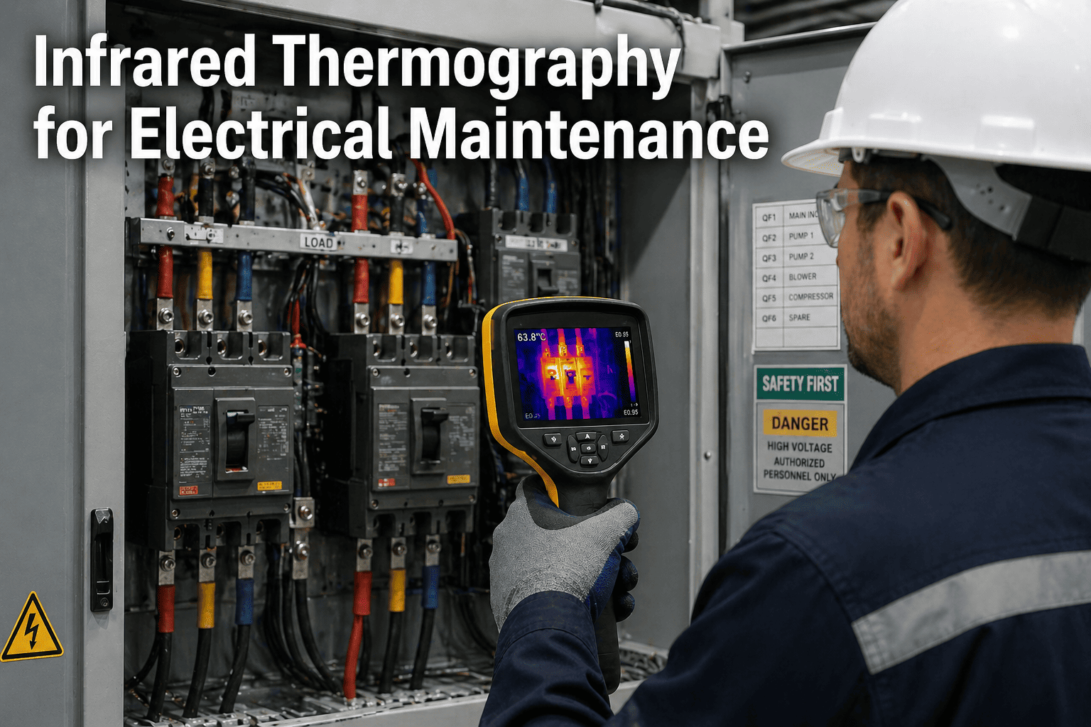
Infrared Thermography for Electrical Maintenance: Prevent Arc Flash & Equipment Failures
NFPA 70B now mandates annual infrared thermographic inspections of all electrical equipment. This guide covers thermal imaging techniques, severity classification, arc flash prevention strategies, and how CMMS integration turns thermal findings into trackable corrective actions.
30%
Of all electrical failures are preceded by detectable thermal anomalies
12 mo
Maximum inspection interval mandated by NFPA 70B (2023)
$1.5M
Average cost of a single arc flash incident including downtime
76%
Of electrical anomalies found are loose or deteriorated connections
Understanding Infrared Thermography
What Is Infrared Thermography for Electrical Maintenance?
Infrared thermography (IRT) uses thermal imaging cameras to detect and visualize heat patterns emitted by electrical components as infrared radiation. Every electrical connection, conductor, and device generates heat during normal operation but abnormal heat signatures indicate impending failures such as loose connections, corrosion, overloading, load imbalance, or insulation breakdown. A trained thermographer can identify these anomalies non-invasively and non-destructively while equipment remains energized and under load, providing a window into electrical health that no other inspection method offers. The 2023 edition of NFPA 70B elevated infrared thermography from a recommended practice to a mandatory inspection requirement, specifying that all electrical equipment within its scope must undergo thermographic inspection at intervals not exceeding 12 months with high-risk "Condition 3" equipment requiring inspection every 6 months. This regulatory shift makes a systematic, CMMS-tracked thermographic program not just best practice, but a compliance imperative. To see how OxMaint structures thermographic inspection workflows with automated scheduling and findings tracking, start a free trial or book a demo.
Types of Thermal Anomalies
Common Electrical Faults Detected by Infrared Thermography
Thermal imaging reveals six primary categories of electrical anomalies. Each requires different corrective actions, priority levels, and CMMS work order workflows. Understanding these patterns enables maintenance teams to classify findings accurately and prioritize repairs based on failure risk rather than subjective judgment.
High Resistance
Loose or Deteriorated Connections
The most common electrical anomaly, accounting for 76% of findings. Loose bolted connections, crimped lugs, and corroded terminals create localized resistance heating. Thermal signatures show concentrated hotspots at connection points with values from 5C to over 100C depending on severity.
76% of all findings
Overloading
Conductor & Component Overheating
Circuits carrying current beyond rated capacity show uniform heating along entire conductor runs or across all phases of a breaker. Unlike connection faults, overloading creates widespread thermal patterns rather than point-source hotspots. Typically indicates undersized conductors or load growth beyond design capacity.
Uniform thermal pattern
Load Imbalance
Phase-to-Phase Temperature Differential
Three-phase systems should show balanced thermal signatures across all phases. A temperature difference exceeding 5C between phases indicates load imbalance, harmonic distortion, or developing single-phase faults. Left uncorrected, imbalance accelerates insulation degradation on the hotter phase.
>5C phase = investigate
Insulation Failure
Dielectric Breakdown Precursors
Degraded insulation on bus bars, cable terminations, and transformer windings creates tracking paths for leakage current, visible as diffuse warm zones rather than sharp hotspots. These precursors can escalate to full insulation breakdown and arc flash within weeks if not addressed.
Arc flash precursor
Harmonics
Non-Linear Load Heating Effects
Variable frequency drives, LED lighting, and switching power supplies inject harmonic currents that cause excessive heating in neutral conductors, transformers, and panels not rated for non-linear loads. Thermal imaging reveals overheated neutrals carrying 150-200% of expected current.
Neutral overheating indicator
Mechanical
Breaker & Switch Mechanism Faults
Internal mechanism wear in circuit breakers and disconnect switches creates abnormal heating from increased contact resistance. Comparing identical breakers carrying similar loads reveals outliers with developing internal faults that will eventually cause failure-to-trip conditions.
Failure-to-trip risk
Industry Pain Points
Why Most Electrical Maintenance Programs Fail at Thermographic Compliance
Despite NFPA 70B mandating annual thermographic inspections, the majority of facilities fall short not because they lack cameras, but because they lack systematic processes to schedule, execute, document, and follow up on findings. These gaps create compounding risk that grows invisibly until a catastrophic event forces attention. If your team recognizes any of these patterns, start a free trial of OxMaint to see how automated inspection workflows close these gaps, or book a demo for a guided walkthrough.
01
Inspections Happen but Findings Disappear
Thermographic reports get filed as PDFs but never generate corrective work orders. Without CMMS integration, the gap between detection and repair grows from days to months often until the same anomaly appears worse on the next scan.
02
No Trend Tracking Across Inspection Cycles
Without historical data linked to specific equipment in CMMS, teams cannot distinguish between stable anomalies and rapidly deteriorating conditions. Each inspection starts from zero context instead of building on prior findings.
03
Scheduling Gaps Miss the 12-Month Window
Manual scheduling leads to missed inspection deadlines, especially for distributed equipment across multiple facilities. NFPA 70B compliance requires documented proof of inspection frequency gaps create audit liability.
04
Arc Flash Risk Not Linked to Thermal Data
Thermal findings and arc flash study data exist in separate systems. When a thermographer identifies a above 40C near an arc flash boundary, the urgency of repair depends on incident energy data that maintenance teams often cannot access.
Severity Classification
NETA/NFPA Thermal Anomaly Severity Classification & Required Actions
| Severity | Range | Priority | Required Action | CMMS Response | Typical Causes |
| Minor |
1-10C |
Low |
Monitor; repair at next scheduled outage |
Planned PM work order |
Slight connection looseness, minor load imbalance |
| Intermediate |
11-20C |
Medium |
Repair within 30 days; increase monitoring frequency |
Corrective WO with 30-day deadline |
Moderate connection resistance, partial corrosion |
| Serious |
21-40C |
High |
Repair at first available opportunity; reduce load if possible |
Emergency WO; escalate to supervisor |
Significant deterioration, advanced corrosion, overloading |
| Critical |
>40C |
Emergency |
Immediate action; consider de-energizing if safe |
Emergency WO; auto-notify safety team |
Imminent failure, severe overload, insulation breakdown |
Arc Flash Prevention
How Infrared Thermography Prevents Arc Flash Incidents
Arc flash events release explosive energy up to 35,000F at the arc point causing severe burns, blast injuries, and equipment destruction in milliseconds. The average cost of a single arc flash incident exceeds $1.5 million when combining medical expenses, equipment replacement, production losses, OSHA penalties, and litigation. Infrared thermography is the most effective non-invasive method to identify the thermal precursors that lead to arc flash: high-resistance connections approaching ignition temperature, insulation degradation creating tracking paths, and overloaded conductors whose dielectric strength is diminishing.
??
IR Windows for Closed-Panel Scanning
Permanently installed IR viewing ports allow thermographic inspection without opening energized panels, eliminating the primary arc flash exposure risk during inspection. NFPA 70E recognizes IR windows as an engineering control that often reduces required PPE category from Level 3-4 to Level 1-2, dramatically improving inspection frequency and compliance.
??
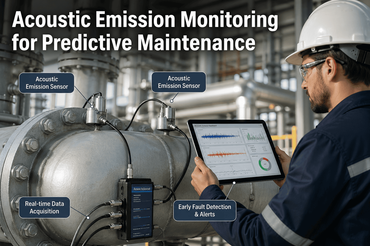
Continuous Thermal Monitoring Systems
IoT-enabled wireless thermal sensors installed inside critical panels provide 24/7 temperature data between manual inspections. When a connection begins trending upward, the CMMS receives automated alerts before the anomaly reaches dangerous levels bridging the gap between annual snapshot inspections where failures can develop undetected.
?
Arc Flash Study Integration
Linking thermal findings with arc flash hazard analysis data in CMMS enables risk-prioritized repairs. A 25C near a panel with 40 cal/cmincident energy demands faster response than the same at a 4 cal/cm location. OxMaint enables this correlation by storing both datasets on the same asset record.
How Oxmaint Solves It
How OxMaint CMMS Transforms Thermographic Inspections into Actionable Maintenance
Most facilities can capture thermal images the breakdown happens between finding an anomaly and fixing it. OxMaint bridges this gap with purpose-built workflows that automate every step from inspection scheduling through corrective action verification. The result is a closed-loop thermographic program that satisfies NFPA 70B compliance, prevents arc flash incidents, and generates measurable ROI. Start a free trial to build your first thermographic inspection route, or book a demo for a personalized walkthrough.
Automated Scheduling
NFPA 70B Compliant Inspection Calendars
Configure 6-month or 12-month thermographic inspection cycles for every electrical asset automatically. OxMaint generates inspection work orders with pre-loaded checklists, routes equipment by location for efficient walkthroughs, and escalates overdue inspections to supervisors before compliance windows close.
Findings Documentation
Thermal Image Capture &Trending
Technicians attach thermal images directly to equipment records in OxMaint, log measurements, severity classification, and recommended actions all from a mobile device. Historical thermal data builds trend lines that reveal whether anomalies are stable or deteriorating across inspection cycles.
Auto Work Orders
Severity-Based Corrective Action Generation
When a thermographer logs a finding above configurable thresholds, OxMaint automatically generates corrective work orders with appropriate priority levels from planned repairs for minor anomalies to emergency work orders with safety team notifications for critical findings exceeding 40C .
Compliance Reporting
Audit-Ready NFPA 70B Documentation
Generate compliance reports showing inspection completion rates, findings by severity, corrective action closure times, and trending anomaly data across your entire electrical infrastructure. One-click export provides the documentation trail auditors and insurance underwriters require.
IoT Integration
Continuous Thermal Sensor Data Ingestion
OxMaint ingests real-time temperature data from wireless thermal monitoring sensors installed in critical panels. When continuous sensors detect temperature excursions between scheduled inspections, automated alerts trigger immediate investigation work orders no manual monitoring required.
Asset Risk Scoring
Thermal + Arc Flash Risk Prioritization
Combine thermal anomaly data with arc flash incident energy ratings, equipment age, and failure history to generate composite risk scores for every electrical asset. Focus repair resources on equipment where thermal degradation intersects with highest arc flash hazard potential.
ROI & Impact
Measurable Returns from CMMS-Integrated Thermographic Programs
$8-$12
Saved per $1 Spent on IR Inspections
Industry-wide ROI for systematic thermographic programs including avoided failures, reduced downtime, and prevented arc flash incidents. Programs with CMMS tracking achieve the higher end of this range.
25%
Reduction in Electrical Unplanned Downtime
Facilities with quarterly thermographic inspections tracked through CMMS report 25% fewer unplanned electrical outages compared to reactive-only programs.
70%
Decrease in Electrical Fire Risk
Comprehensive thermographic programs with CMMS-enforced corrective action timelines reduce electrical fire incidents by up to 70% by catching thermal precursors months before ignition conditions develop.
100%
NFPA 70B Audit Compliance Rate
OxMaint users maintaining automated inspection schedules achieve 100% on-time inspection completion rates with full documentation trails that satisfy the most rigorous auditor scrutiny.
Expert Answers
Frequently Asked Questions: Infrared Thermography for Electrical Maintenance
How often should infrared thermographic inspections be performed on electrical equipment?
NFPA 70B (2023 edition) mandates infrared thermographic inspections at intervals not exceeding 12 months for all electrical equipment within its scope. Equipment classified as "Condition 3" those previously found with urgent anomalies or those that missed scheduled inspections requires inspection every 6 months. Critical infrastructure such as main switchgear, large transformers, and high-incident-energy panels benefit from quarterly inspections. OxMaint CMMS automates these varying frequencies, assigning appropriate inspection intervals to each asset and generating work orders automatically.
Start a free trial to configure your compliance calendar.
What minimum load conditions are required for accurate thermographic inspections?
Thermographic inspections should be performed under normal operating load conditions to ensure anomalies are visible. If normal loading is not feasible, NFPA 70B permits testing at a minimum of 40% of nominal circuit loading. Below this threshold, many thermal anomalies particularly loose connections and overloading conditions may not generate sufficient heat differential to be detected. OxMaint helps coordinate inspection timing with production schedules to ensure adequate load conditions.
Book a demo to see scheduling coordination features.
What is the difference between qualitative and quantitative thermographic inspections?
Qualitative inspections compare similar components under similar conditions to identify relative temperature differences useful for screening large numbers of connections quickly. Quantitative inspections measure actual surface temperatures and calculate precise values referenced against ambient or similar components, enabling severity classification per NETA/NFPA standards. A comprehensive program uses qualitative scanning to identify anomalies and quantitative measurement to classify severity. OxMaint supports both approaches with flexible inspection checklists and recording fields.
How do IR windows improve safety during thermographic inspections?
IR windows are permanently installed viewing ports made of infrared-transparent materials (crystal or polymer) that allow thermal imaging through closed, energized panels. They eliminate the need to remove panel covers the primary arc flash exposure risk during thermographic inspections. NFPA 70E recognizes IR windows as an engineering control that typically reduces the required PPE category from Level 3-4 to Level 1-2, making inspections faster, safer, and more likely to be performed on schedule. OxMaint tracks IR window locations and inspection routes for optimal coverage.
Start a free trial to map your IR window routes.
Can infrared thermography replace other electrical testing methods?
No infrared thermography is a powerful complement to, not replacement for, other electrical testing methods. It excels at detecting thermal anomalies in energized equipment but cannot identify issues that do not produce heat signatures, such as insulation resistance degradation below loading, improper grounding, or protective relay misconfiguration. A comprehensive electrical maintenance program combines thermography with insulation resistance testing, power quality analysis, protective device testing, and visual inspections. OxMaint CMMS coordinates all these inspection types on integrated schedules.
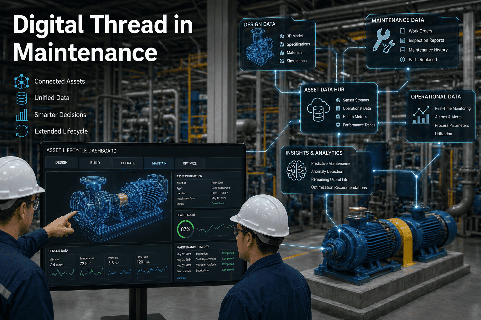
How does CMMS integration improve thermographic inspection programs?
CMMS integration transforms thermographic inspections from isolated events into continuous improvement programs. Key benefits include: automated scheduling that ensures no equipment misses its inspection window; digital documentation linking thermal images and measurements directly to asset records; automatic corrective work order generation based on severity thresholds; historical trend tracking that reveals deterioration patterns across inspection cycles; and compliance reporting that proves program effectiveness to auditors and insurers. OxMaint delivers all these capabilities in a mobile-first platform.
Book a demo to see the complete workflow.
Start Today
Stop Filing Thermal Reports That Never Generate Repairs
OxMaint CMMS turns every thermographic finding into a tracked, prioritized work order from automated NFPA 70B inspection scheduling to severity-based corrective action workflows. Close the gap between thermal detection and electrical repair before your next anomaly becomes an arc flash incident.