Steam turbine maintenance in 2026 is no longer about reacting to vibration alarms or waiting for the next forced outage — it's about building a structured, section-by-section program that treats the HP, IP, and LP turbines as distinct machines with distinct failure modes. A single missed gland seal inspection can cost 0.5–1.5% in heat rate; a thrust bearing failure can write off an entire rotor. This guide gives power plant maintenance and reliability managers the complete framework — blade inspection intervals, bearing care, valve testing, lube oil management, and overhaul cadence — and shows how a CMMS like OxMaint (start free) turns that framework into scheduled, tracked, auditable work. If you'd rather see it configured for your plant first, book a 30-minute demo.
Steam Turbine Maintenance Guide for Power Plants — CMMS-Driven Program for 2026
The complete HP/IP/LP maintenance framework: blade inspection, gland seals, thrust bearings, valve testing, lube oil systems, and overhaul planning — built for maintenance and reliability managers who need a system of record, not a binder of PDFs.
Why HP, IP, and LP Sections Need Separate Maintenance Strategies
The single biggest mistake in steam turbine maintenance is treating the entire machine as one asset with one PM schedule. The high-pressure (HP), intermediate-pressure (IP), and low-pressure (LP) sections operate under fundamentally different thermal, mechanical, and chemical conditions — and they fail in fundamentally different ways.
- Creep and thermal fatigue dominate
- Solid particle erosion (SPE) from boiler carryover
- Nozzle block and diaphragm cracking
- First-stage blade root cracking
- Bolt relaxation on high-temp casings
- Creep-fatigue interaction at blade attachments
- Stress corrosion cracking (SCC) in disc bores
- Diaphragm dishing from pressure differential
- Steam path fouling reducing efficiency
- Intercept valve stem wear
- Water droplet erosion on last-stage blades (L-0, L-1)
- Corrosion fatigue in the Wilson line region
- Pitting and SCC on blade surfaces
- Blade root and shroud cracking
- Exhaust hood and condenser interface issues
Blade Inspection Practices and Stage-Specific Failure Modes
Blade failures account for roughly 40% of all steam turbine forced outages. The inspection method, interval, and acceptance criteria must match the stage — a one-size-fits-all approach misses the defects that actually cause failures.
| Stage / Location | Primary Failure Mode | Inspection Method | Interval (Fired Hours) | Acceptance Criteria |
|---|---|---|---|---|
| HP Stage 1 (control stage) | Creep cracking, SPE | Borescope + PT + UT | 8,000–12,000 | No crack indications; erosion < 10% chord loss |
| HP Stages 2–N | Thermal fatigue, erosion | Borescope visual | 12,000–25,000 | No cracks; erosion within OEM limits |
| IP Stages (all) | SCC in disc bores, creep-fatigue | UT disc bore + visual blades | 25,000–50,000 | No UT indications > 1mm; no blade cracks |
| LP L-0 (last stage) | Water droplet erosion, corrosion fatigue | Visual + PT + dimensional check | 12,000–25,000 | Erosion < OEM limit; no pitting > 0.5mm depth |
| LP L-1 | Erosion, SCC | Visual + PT | 12,000–25,000 | No cracks; erosion shields intact |
| LP L-2 and earlier | Corrosion fatigue, fouling | Visual + spot PT | 25,000–50,000 | No crack indications; fouling removable |
Gland Seal and Packing Maintenance — The Silent Efficiency Killer
Gland steam seals prevent steam from leaking out at the HP/IP shaft penetrations and air from leaking in at the LP end. When seal clearances open up — through rubbing during startup transients, thermal bowing, or simple wear — the consequences are measurable and expensive.
What Degraded Seals Cost You
- Heat rate penalty: 0.5–1.5% increase from HP/IP seal leakage bypassing stages
- Capacity loss: 1–3 MW on a 500 MW unit from LP air in-leakage reducing vacuum
- Water chemistry stress: air in-leakage raises dissolved O₂, accelerating boiler corrosion
- Gland steam system overload: excessive seal steam demand stresses the supply header and desuperheater
Seal Maintenance Program
- Every startup: monitor gland steam pressure and temperature trends; log anomalies
- Every minor outage (8,000–12,000 hrs): visual inspection of accessible seal segments; check for rub marks
- Every major outage: remove and measure all seal ring clearances; replace springs; check segment flatness
- Clearance targets: OEM-specified radial clearances typically 0.010–0.025" depending on location — log as-found and as-left values
- Upgrade evaluation: brush seals or retractable seals can reduce leakage 50–80% vs. labyrinth — track ROI in your CMMS
Thrust and Journal Bearing Care — Protecting the Rotor
The thrust bearing maintains axial rotor position within thousandths of an inch. Journal bearings support the rotor's weight and control radial vibration. Both are oil-lubricated, both are instrumented, and both give you warning — if you're monitoring and trending the data.
| Parameter | Normal Range | Alarm | Trip | Trending Frequency |
|---|---|---|---|---|
| Thrust bearing metal temp | 180–220°F | 230°F | 250°F | Continuous (DCS) + daily log |
| Axial rotor position | ±0.010" from center | ±0.015" | ±0.020" | Continuous (proximity probes) |
| Journal bearing metal temp | 160–200°F | 220°F | 240°F | Continuous + daily log |
| Shaft vibration (peak-to-peak) | < 3 mils | 4 mils | 6 mils | Continuous + weekly trend review |
| Lube oil supply pressure | 18–25 psig | 15 psig (low) | 12 psig (trip) | Continuous |
| Lube oil supply temp | 110–130°F | 140°F (high) | — | Continuous + daily log |
Main and Control Valve Maintenance — Your Overspeed Protection
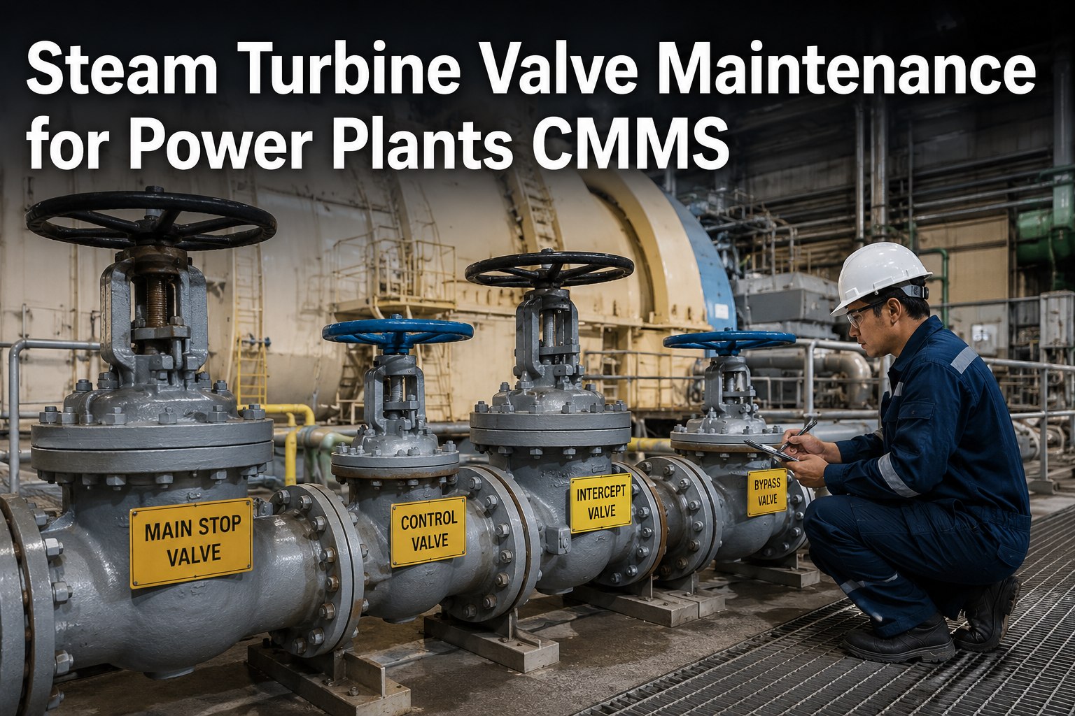
Main stop valves, control (governor) valves, reheat stop valves, and intercept valves are the turbine's primary defense against overspeed. A stuck valve during a load rejection can destroy the machine in seconds. Valve testing and maintenance are non-negotiable.
Online Partial-Stroke Testing
Exercise each main stop valve and control valve 10–15% stroke weekly (or per OEM). Confirms freedom of movement without load impact. Log stroke time and any hesitation in your CMMS as a condition record.
Full-Stroke Testing
Perform full-stroke tests during planned outages or at reduced load per OEM procedure. Verify closure time meets spec (typically < 0.5 seconds for main stop valves). Record as-found closure times.
Valve Internal Inspection
At every major outage: inspect valve seats, stems, bushings, and discs for erosion, cracking, and steam cutting. Check stem packing. Measure stem-to-bushing clearances. UT valve bodies for thermal fatigue cracking at stress concentration points.
Actuator and Hydraulic System Service
Change hydraulic fluid filters every 2,000–4,000 hours. Test servo valves annually. Check accumulator pre-charge quarterly. Verify trip solenoid function at every test. Log all fluid analysis results.
Lube Oil System — The Lifeblood of Turbine Reliability
Every bearing, every hydraulic actuator, and the turning gear all depend on clean, cool, properly pressurized lube oil. Oil-related failures are among the most preventable in the plant — and among the most common when the lube oil system is treated as "set and forget."
Oil Quality Management
- Monthly oil analysis: viscosity, water content, particle count (ISO 4406), acid number, metals
- Target cleanliness: ISO 16/14/11 or better for turbine lube oil
- Water content < 200 ppm (500 ppm absolute max)
- Varnish potential (MPC) testing quarterly on units > 10 years old
- Log every result in CMMS with trend alerts
System Component PM
- Main oil pump: vibration check monthly, overhaul at major outage
- AC auxiliary pump: auto-start test weekly
- DC emergency pump: auto-start test weekly, battery check monthly
- Oil coolers: clean and inspect annually, check for tube leaks
- Reservoir: drain and clean at every major outage
- Vapor extractor: verify operation monthly
Filtration and Purification
- Full-flow filters: change on differential pressure (> 25 psid) or quarterly
- Bypass/kidney-loop filtration: run continuously, change elements per DP
- Vacuum dehydrator: deploy when water > 300 ppm or after cooler tube leak
- Electrostatic varnish removal: continuous on units with MPC > 30
- Track all filter changes and purification run-hours in CMMS
Major Overhaul Cadence — Putting It All Together
The sections above don't operate in isolation. They converge into a major overhaul cycle that must be planned, budgeted, and tracked as a single integrated program. Here's how the cadence typically structures for a utility-scale steam turbine in 2026.
How OxMaint CMMS Centralizes Your Steam Turbine Program
Every section of this guide generates data — inspection results, clearance measurements, oil analysis reports, valve test records, vibration trends, overhaul findings. Without a CMMS purpose-built for power plant asset hierarchies, that data lives in spreadsheets, binders, and tribal knowledge. Here's how OxMaint structures it.
HP/IP/LP Asset Hierarchy
Model your turbine as a parent asset with HP, IP, and LP sections as children — each with their own sub-components (blades, seals, bearings, valves). Every PM, inspection, and work order attaches to the exact component, building a complete lifecycle history per section.
PM by Fired Hours or Starts
Schedule PMs by calendar, fired hours, equivalent starts, or condition triggers — matching how turbine maintenance actually works. OxMaint auto-generates work orders when thresholds hit, so your 8,000-hour borescope inspection never slips because someone forgot to check the hour meter.
Reliability Trending
Track axial position drift, bearing temperature trends, seal clearance history, and oil analysis results over time. Spot the 0.003" thrust position shift before it becomes a trip. Compare heat rate impact before and after seal replacement. Build the data case for overhaul timing.
Digital Inspection Checklists
Convert every inspection table in this guide into a mobile checklist. Technicians record findings, photos, and measurements on a tablet at the turbine deck — no transcription, no lost paper, no illegible handwriting on a clearance record.
Overhaul Project Management
Structure your major overhaul as a project with hundreds of linked work orders, parts reservations, contractor assignments, and milestone tracking. Capture as-found/as-left data that feeds directly into the next overhaul's scope definition.
OEM Bulletin and Document Control
Link OEM service letters, inspection bulletins, and technical procedures to the specific turbine components they affect. When a new blade inspection bulletin drops, you know instantly which assets and PMs need updating.
Frequently Asked Questions
How often should I inspect steam turbine blades?
What's the most common cause of steam turbine forced outages?
How do I know when to schedule a major overhaul vs. another minor outage?
Can a CMMS really help with steam turbine maintenance, or is it just for scheduling?
What lube oil parameters should I trend, and how often?
Build Your 2026 Steam Turbine Program on a System of Record
Stop managing your most critical rotating asset with spreadsheets and tribal knowledge. OxMaint gives your team HP/IP/LP asset hierarchies, fired-hour PM scheduling, digital inspection checklists, and reliability trending — in one platform built for power plants.