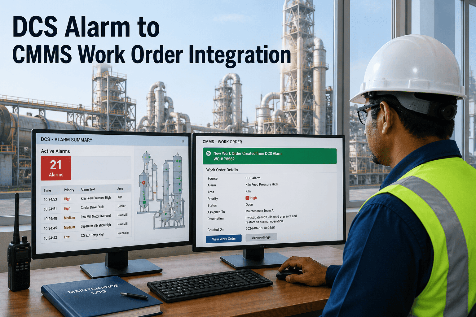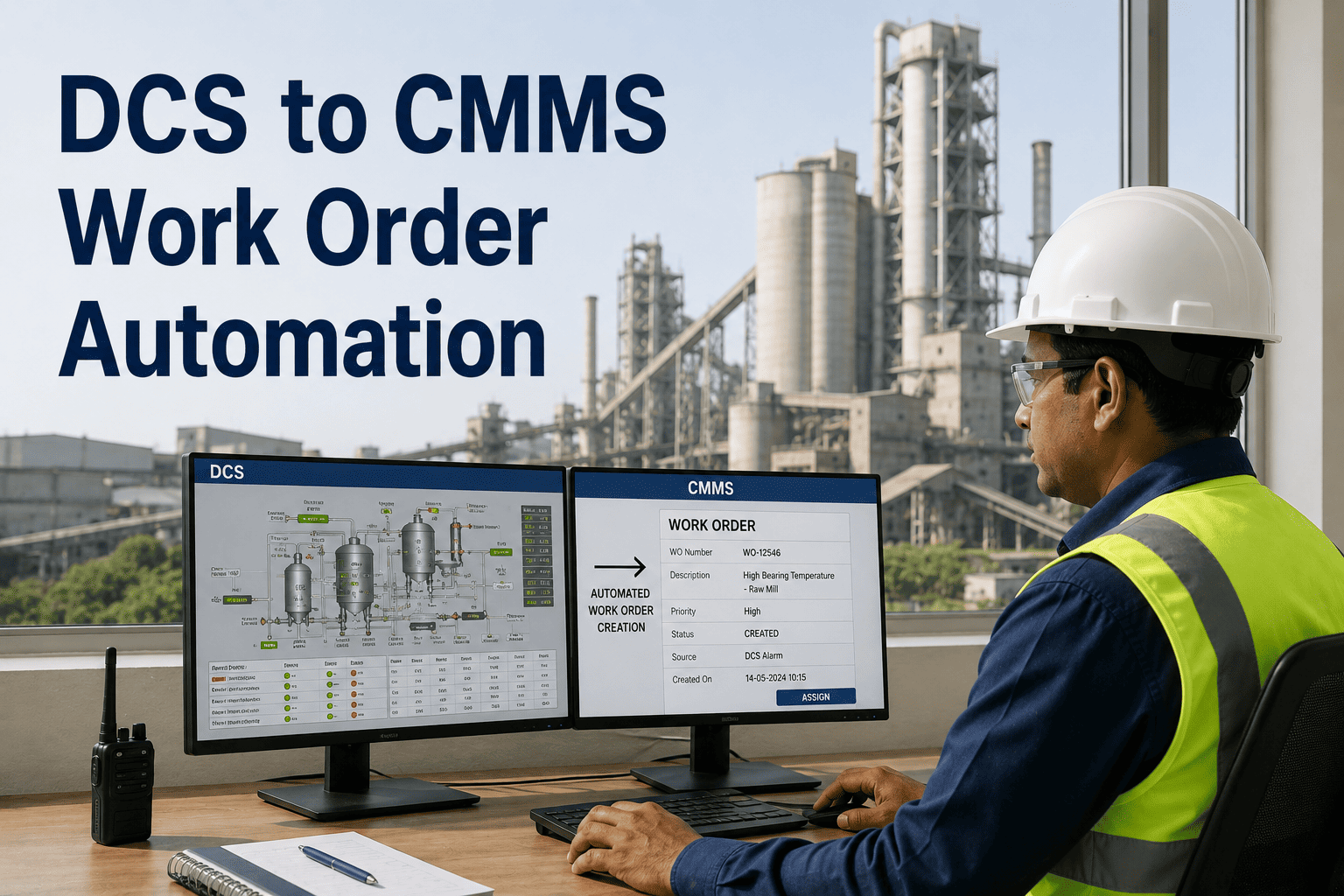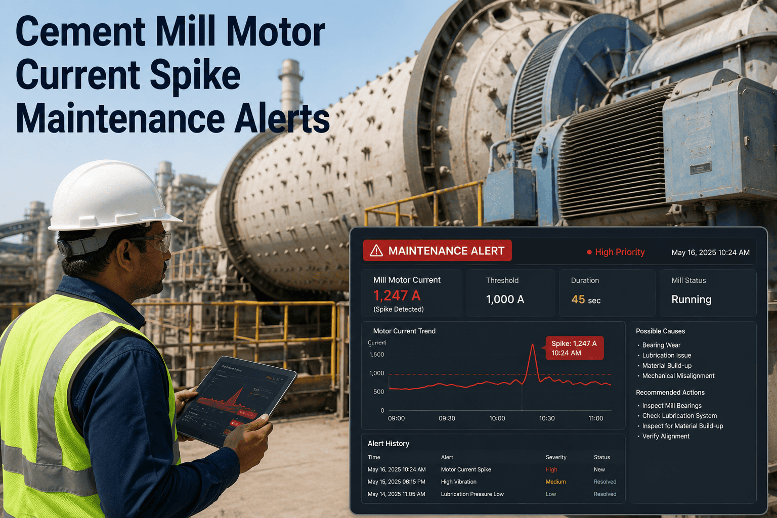
The cement mill main drive motor speaks in current. A clean grinding load reads a stable signature within a narrow band around design amperage. A spike points to a chunk in the feed, a slipping coupling, or a bearing seizing toward shutdown. A sustained drop below normal points to material buildup, a blinded diaphragm, or charge segregation that is starving the grinding zone. Both signals are detectable in real time from a single sensor clamp on the motor cable — and both are routinely missed when the data sits in a SCADA historian that no maintenance engineer is paid to monitor minute by minute. The gap between a current signature deviating and a work order arriving at the right technician's queue is where most unplanned mill shutdowns are born. To see how OxMaint closes that gap with IoT-driven current monitoring and automated work order generation, book a 30-minute walkthrough or start a free trial.
Cement Plant Grinding · IoT Integration · Motor Current Alerts
Cement Mill Motor Current Spike Maintenance Alerts
A spike is rarely the first signal. By the time the trip relay fires, the IoT signature has usually been drifting for hours or days. Read the drift, not the trip — and turn every threshold breach into a tracked work order before the next shift.
Without IoT-driven current alerts
$127K
Emergency repair, collateral shaft damage, 4.5 days lost production from a single bearing failure that escalated unmonitored
Response time after sensor spike: 14 hours
Lead time before failure: Often weeks lost
With IoT alert workflow
$4.2K
Planned replacement during scheduled downtime with parts staged, after current and vibration trends crossed configured Warning threshold
Response time after sensor spike: 23 minutes
Lead time before failure: 37 days documented
The signature library
Seven Patterns the Motor Current Trace Will Show You
Motor current is not a single number — it is a continuous signature with a recognisable healthy shape and a small set of distinct deviation patterns. Each pattern points to a different root cause inside the mill or upstream of it. A monitoring programme that knows the seven patterns can route every detection event to the right corrective work order in the CMMS without manual triage. The cards below map each pattern to its likely cause and the action it should generate.
Pattern 01
Stable Band
Current oscillating in a narrow band around design amperage with grinding sound steady and discharge constant
Healthy mill operation under design load and normal feed rate
ActionNo work order. Logged as Normal baseline reading.
Pattern 02
Sustained Drop
Current drifting downward toward 70% of normal with grinding sound dulling and discharge volume falling
Mill buildup — swollen belly or blind mill from overfeed, wet feed, or partition screen blockage
ActionFeed rate review and diaphragm inspection work order generated.
Pattern 03
Step Increase
Current rising 15 to 20% above baseline at the same feed rate, sustained over multiple shifts
Bearing degradation, liner unbalance from uneven wear, or gear transmission losses increasing rotational drag
ActionVibration survey and bearing inspection work order created.
Pattern 04
Sharp Transient Spike
Single brief excursion well above normal that returns to baseline within seconds — often without a relay trip
Material chunk in feed, momentary charge slip, or transient mechanical interference inside the mill
ActionEvent logged for trend. Inspection if frequency increases.
Pattern 05
Rising Oscillation
Amplitude of current swings widening around the mean while mean remains close to baseline
Feed instability, charge segregation, or developing imbalance in the grinding media distribution
ActionFeed system check and ball charge audit work order issued.
Pattern 06
Sustained High Plateau
Current locked above normal for an extended period with stable mean and reduced oscillation amplitude
Heavy load condition, harder feed material, or over-filled mill operating at the boundary of design capacity
ActionOperations review and grindability sample work order generated.
Pattern 07
Rotor Bar Signature
Current spectrum showing sidebands around line frequency at twice the slip frequency on motor current signature analysis
Broken or cracked rotor bars, end ring damage, or air gap eccentricity inside the motor itself
ActionElectrical maintenance team dispatched for motor diagnostics.
Data path
From Clamp Sensor to Closed Work Order — Five Hops in Under a Minute
An IoT-enabled motor current monitoring architecture moves data through five distinct layers, from the physical clamp around the motor cable to the corrective work order assigned in the maintenance technician's mobile inbox. Each layer adds a specific function — sensing, edge processing, transport, AI evaluation, and CMMS dispatch — and each is configurable independently. Understanding the layers is the difference between deploying sensors and deploying a working alert system.
Layer 1
Sensor Node
Split-core current transformer clamped on one phase of the motor cable, sampling at 5 kHz with edge electronics that compute RMS current, peak current, and trend features locally
Layer 2
Edge Hub
Local gateway running anomaly detection on the streaming current data, filtering noise, compressing time-series, and buffering during connectivity gaps so no diagnostic data is lost
Layer 3
Transport
MQTT or OPC-UA stream from the edge hub to the OxMaint platform via plant WiFi, dedicated LoRaWAN gateway, or wired Ethernet depending on plant connectivity architecture
Layer 4
AI Evaluation
Asset-specific baseline comparison against the learned current signature for that motor under current operating mode, with multi-parameter fusion against vibration and temperature inputs
Layer 5
Work Order
Threshold breach generates a pre-populated CMMS work order with asset reference, fault pattern, recommended action, parts list, and assignment based on technician skill and shift
Three-tier alert framework
Why a Single Threshold Generates Alert Fatigue and What to Configure Instead
A single fixed alarm threshold on motor current is the most common cause of failed IoT programmes. Either the threshold is set too tight and generates noise that maintenance teams learn to ignore, or it is set too loose and misses the early signature drift that gives the most lead time. A three-tier framework with distinct Advisory, Warning, and Critical bands solves both problems — each tier triggers a different response, and the cumulative pattern across tiers reveals the trajectory of the developing fault.
Advisory Tier
TriggerCurrent deviation 3 to 5% from learned baseline sustained over 4 hours
ResponseNo immediate action. Logged to asset trend record. Reviewed at next daily reliability standup
RoutingReliability engineer dashboard tile
Work orderNot generated automatically
Warning Tier
TriggerCurrent deviation 5 to 10% from baseline OR Advisory persisting beyond 24 hours
ResponseScheduled inspection within 48-hour window. Vibration cross-check requested
RoutingDay shift mechanical lead, mobile work order push notification
Work orderGenerated automatically with parts pre-listed
Critical Tier
TriggerCurrent deviation above 10% OR multi-parameter confirmation OR sharp spike with vibration confirmation
ResponseImmediate intervention required. Operations notified to derate or stop feed
RoutingOn-shift maintenance + supervisor escalation, SMS and mobile push
Work orderGenerated with priority flag and escalation timer
OxMaint IoT Integration for Cement Grinding
Connect Existing Current Sensors to Automatic Work Order Generation in 90 Days
OxMaint integrates with major industrial IoT platforms via MQTT, OPC-UA, and REST API — Siemens MindSphere, PTC ThingWorx, AWS IoT Core, Azure IoT Hub, and direct edge sensor nodes. Threshold breaches on motor current become pre-populated work orders with the parameter trend attached, the affected asset linked, and the right technician assigned. Sensor-to-work-order latency drops from 14 hours to under 25 minutes documented in deployed cement plants.
Multi-parameter fusion
Why Current Alone Triggers False Alarms — and What to Combine It With
A current spike taken in isolation is ambiguous. It could be a developing fault, a transient load excursion, or a feed system irregularity. When the current signal is fused with vibration and temperature data from the same motor and gearbox, ambiguity collapses to a small set of definitive root causes. Fused multi-parameter alerts reduce false positive rates significantly compared with single-parameter thresholds — typically below 8% after sixty days of calibration on a stable installation. The fusion logic below shows the standard three-input combinations and the fault patterns each one resolves.
Current rise + Vibration rise + Temperature rise
Confidence above 90%
Bearing inner-race or outer-race defect entering active wear phase. Defect frequency typically detectable 12 to 15 dB above baseline at this stage. Work order: vibration spectral analysis and bearing inspection at next planned window.
Current drop + Acoustic dampening + Discharge volume drop
Confidence above 85%
Mill buildup progressing toward swollen belly condition. Work order: feed rate reduction, diaphragm and partition screen inspection, charge audit if buildup is persistent.
Current sidebands + Vibration at 2x line frequency + Temperature stable
Confidence above 88%
Broken rotor bar or end ring damage detected by motor current signature analysis. Work order: electrical diagnostic team dispatched, motor scheduled for offline test at next shutdown.
Current oscillation widening + Vibration imbalance signature
Confidence above 80%
Grinding media charge imbalance or liner uneven wear creating rotational asymmetry. Work order: charge audit, liner thickness gauging, and rebalancing intervention.
Current stable + Vibration rising + Temperature rising
Confidence above 75%
Lubrication degradation or seal failure in the bearing housing without yet affecting mechanical load. Work order: oil sample, seal inspection, grease replenishment review.
Implementation roadmap
Six Phases From First Sensor to Active Predictive Alerts
A working motor current monitoring programme is not built by mounting sensors. It is built by mounting sensors, learning the baseline, configuring the tier thresholds, validating the alert routing, and tuning the false positive rate over the first ninety days. The phased roadmap below captures the implementation sequence that cement plants follow to move from sensor purchase to active predictive alerts with documented work order outcomes.
Phase 01
Asset Criticality Mapping
Rank mill drive motors by failure consequence and downtime cost. Confirm top-tier coverage for cement mill, raw mill, and coal mill main drives before extending to auxiliary drives.
Phase 02
Sensor Installation
Mount split-core current transformers on each monitored phase, connect to the edge hub with the appropriate wireless or wired protocol, and verify data ingestion into OxMaint asset records.
Phase 03
Baseline Learning
Allow 14 to 30 days of normal operating data to flow into the AI baseline model, capturing the current signature across product changes, shift patterns, and feed grindability variations.
Phase 04
Threshold Configuration
Configure the Advisory, Warning, and Critical bands per motor using the established baseline. Define multi-parameter fusion rules where vibration and temperature data are available.
Phase 05
Work Order Routing
Set up the work order rules per tier — fault type, asset reference, technician assignment, parts list, escalation timer. Validate routing against shift schedules and skill matrices.
Phase 06
Tune and Scale
Review the first 60 to 90 days of alerts. Tighten or relax thresholds to keep false positives below 8%. Extend coverage to the next tier of grinding circuit assets and gearbox child records.
Frequently asked questions
Cement Mill Motor Current Monitoring — Plant Engineer Questions
Motor current is a high-value primary signal but not a complete predictive maintenance solution. Current detects load changes that point to mill buildup, charge imbalance, drive train friction, and certain motor electrical faults — all critical signatures. It does not directly detect early bearing defect frequencies or thermal anomalies in the gearbox housing. A practical cement mill IoT programme combines current monitoring with triaxial accelerometers on trunnion bearings and surface temperature sensors on the bearing housings and motor frame. The three signals together provide multi-parameter fusion that reduces false positives below 8% after about 60 days of calibration, which is materially better than any single-parameter threshold can achieve.
A sustained current drop is the classic signature of mill buildup, also called swollen belly or blind mill. When the partition screen blinds, when overfeed accumulates on the liner, or when wet material agglomerates inside the chamber, the grinding zone loses its impact dynamics. The steel balls cushion against material rather than tumbling freely, the grinding sound dulls, and the motor sees less load — current drops toward 70% of normal. A monitoring programme that only watches for spikes will miss this entirely. Both spike and drop signatures must be configured as alert conditions in the IoT integration, mapped to different root cause work order templates.
Motor current signature analysis takes the raw current waveform sampled at high frequency and applies frequency-domain transforms to extract specific spectral features. Where a basic current monitor reports RMS amperage versus baseline, signature analysis identifies sidebands around the line frequency that correspond to broken rotor bars, end ring damage, air gap eccentricity, and certain stator winding faults. The analysis is performed without any sensor in physical contact with the motor itself — only the cable clamp is required. For cement mill main drives, motor current signature analysis catches electrical degradation modes that mechanical vibration sensors cannot see, and it should be part of the IoT data pipeline for any high-criticality motor. OxMaint ingests current signature data directly into the asset record for trending.
OxMaint uses configurable de-duplication and tier-based escalation to prevent alert fatigue. A cooldown window can be defined per asset and sensor type — for example, only one work order per asset per four-hour window for the same fault condition. Additional sensor readings during the cooldown update the open work order's sensor data rather than creating new tickets. The three-tier framework also ensures that Advisory tier signals do not generate work orders at all — they log to the asset trend for engineer review at the next standup. Only Warning and Critical tier breaches generate work orders, and the multi-parameter fusion logic further confirms that the breach reflects a genuine developing fault rather than a transient excursion.
OxMaint integrates with the standard industrial IoT protocols used in cement plant environments — MQTT for lightweight edge-to-cloud transport, OPC-UA for PLC and DCS connectivity, REST API for cloud platforms, and Modbus TCP for legacy automation systems. On the platform side, OxMaint connects natively with AWS IoT Core, Azure IoT Hub, Siemens MindSphere, PTC ThingWorx, and Losant. For edge devices sending raw sensor data, OxMaint can receive MQTT messages directly without an intermediate IoT platform — which is the simplest path for cement plants deploying low-cost wireless current sensors. Book a walkthrough to review the integration architecture against the plant's existing automation stack.
OxMaint · IoT Integration for Cement Mill Drives
Turn Every Current Signature Deviation Into a Tracked, Closed, Auditable Work Order
A motor current spike that nobody acts on is not a maintenance event — it is a missed warning that costs production. OxMaint connects existing IoT sensors on cement mill drives to automated work order generation, multi-parameter fusion alerts, mobile-first technician routing, and audit-ready asset records — so the gap between sensor reading and maintenance action closes from days to minutes, and unplanned shutdown weeks become planned intervention hours.