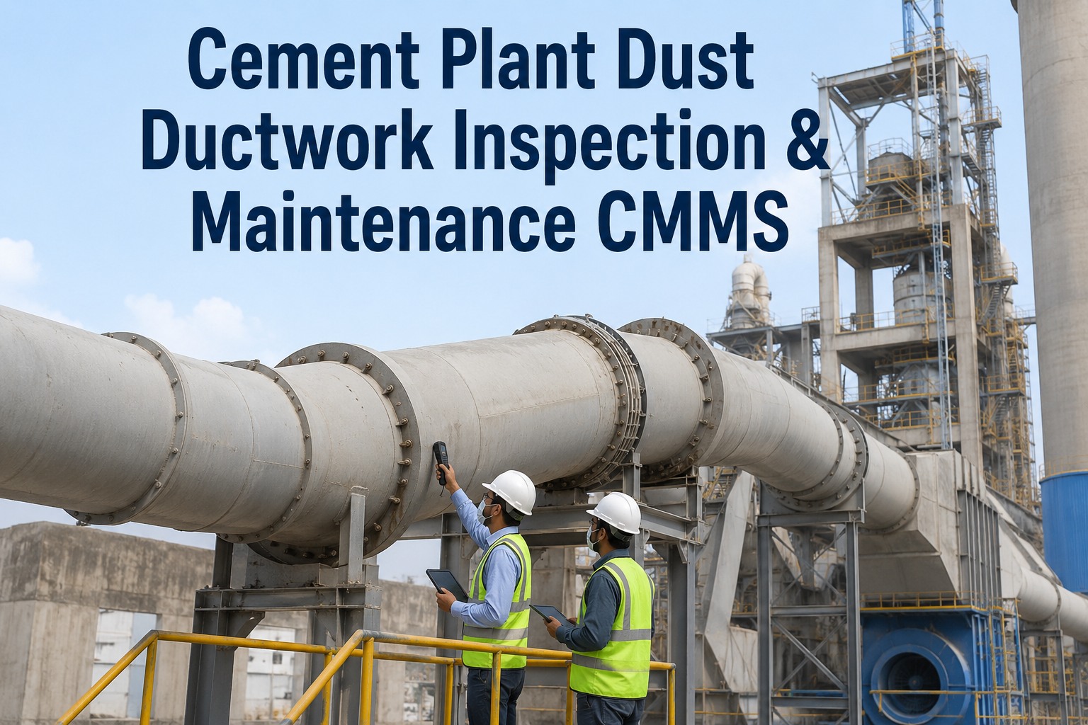
The diaphragm pulse jet valve is one of the smallest components in a cement plant baghouse and one of the most consequential. When a single valve fails to fire, the dust cake on its assigned row of bags continues to thicken, differential pressure climbs, the ID fan loads harder, and within hours the stack opacity reading drifts toward the regulatory ceiling. Most plants discover the problem only when the CEMS exception report lands on the environment engineer's desk — by which point the kiln draft has already been suffering, compressed air consumption has spiked, and the next CPCB stack test is days away. This checklist consolidates the inspection cadence, diagnostic methods, failure signatures, and CMMS record structure that keep every pulse jet valve in the dust collector firing on schedule. To see how OxMaint runs valve-by-valve PM tracking and compliance archiving for cement baghouses, book a 30-minute walkthrough or start a free trial.
Cement Plant Maintenance · Pulse Jet Valves · Inspection Checklist
Cement Plant Dust Collector Pulse Jet Valve Maintenance Checklist
Diaphragm wear, solenoid coil drift, moisture in pulse air, and timer miscalibration each leave a different signature in the baghouse. Catch them in inspection cycles — not in CEMS exception reports.
99.9%
Particulate removal achievable when every valve fires reliably
30 mg/Nm³
Typical CPCB particulate ceiling on a modern cement stack
12–24 mo
Recommended diaphragm replacement window for continuous duty
65%
Documented header pressure loss at the last bag from leaking valves
Inside one pulse
The Four-Phase Cycle Every Valve Must Complete in Under a Second
A pulse jet valve is judged by one criterion: does it deliver a sharp, full-amplitude burst of compressed air into its blow pipe within the firing window and reseal cleanly afterwards. Each phase of the cycle has its own characteristic failure mode. Understanding the cycle is the foundation for both the diagnostic test methods and the inspection cadence that follow.
Phase 01
Pilot Pressurised
Compressed air enters the valve body and fills the pilot chamber above the diaphragm. The pressure differential across the diaphragm holds the main passage sealed against the header. A weak or leaking solenoid pilot port at this phase shows up as continuous air bleed and reduced header pressure across the manifold.
Phase 02
Solenoid Triggers
The timer board sends an electrical signal to the solenoid coil. The solenoid lifts, opening the pilot exhaust port and dumping the pilot chamber pressure. A failed coil, corroded terminal, or loose wiring at this phase produces a misfire — the valve never opens and that row of bags goes uncleaned for the entire cycle.
Phase 03
Diaphragm Lifts
With pilot pressure collapsed, header pressure pushes the diaphragm clear and a high-volume burst of compressed air rushes into the blow pipe and down through the bags. A torn, hardened, or fatigued diaphragm at this phase delivers a weak or partial pulse, leaving residual dust cake on the assigned filter row.
Phase 04
Reseal & Recharge
The solenoid de-energises, the pilot port closes, and pilot pressure rebuilds. The diaphragm reseats and the header recharges within roughly 0.3 seconds, ready for the next cycle. A spring-fatigued or improperly seated diaphragm at this phase leaks continuously, consuming compressed air and reducing the next pulse intensity.
Failure signatures
Match the Symptom to the Root Cause — Before Replacing Parts
Pulse jet valve failures rarely arrive as outright stoppage. They drift in as elevated differential pressure, rising compressor load, or intermittent opacity spikes. Each of the failure modes below has a distinct symptom-cause-fix pattern. Logging the symptom code on the work order at the time of inspection is what lets reliability engineers correlate failures with operating conditions, water quality, and air supply integrity over the next twelve months.
High Severity
Diaphragm Tear or Crack
SymptomContinuous compressed air leak audible at exhaust port, header pressure cannot recover between pulses, dP across baghouse climbs steadily.
Root CauseDiaphragm rubber fatigue past service life, moisture-driven aging, or asymmetric deformation from undersized valve paired with oversized blow pipe.
ActionReplace diaphragm kit. Inspect compressed air dew point and oil content. Verify valve diameter matches blow pipe specification.
High Severity
Solenoid Coil Failure
SymptomValve does not fire on its scheduled slot, assigned bag row stays loaded, localised dP rise on that compartment, no audible discharge.
Root CauseCoil burnout from voltage spikes, corroded terminal connections in humid baghouse environment, or open-circuit winding failure.
ActionMeasure coil resistance against specification. Replace coil and tighten terminal connections. Inspect adjacent coils for shared cause.
Medium Severity
Moisture in Pulse Air
SymptomDust cake wet-sets on bag surfaces, normal pulses fail to dislodge cake, dP recovery after pulse is poor across the entire manifold.
Root CauseFailed moisture separator, blocked auto-drain, dew point above ambient temperature in the receiver, or absent air dryer downstream of compressor.
ActionVerify auto-drain discharge at each round. Inspect dryer regeneration cycle. Bring offline if wet-set cake is widespread.
Medium Severity
Spring Fatigue / Slow Reseal
SymptomValve action sounds soft or extended, faint continuous hiss between firings, header pressure at last bag well below front-bag pressure.
Root CauseReturn spring weakening over millions of cycles, allowing partial valve opening between pulses and continuous compressed air bleed.
ActionReplace full diaphragm kit including spring. Re-survey header pressure at first, middle, and last bag positions after repair.
Low Severity
Timer / Controls Drift
SymptomPulse intervals are too short for low-dust gas, compressed air consumption rises, bag wear accelerates from over-pulsing on lightly loaded surfaces.
Root CauseFixed-timer cleaning scheme not matched to actual dust loading, or timer board configuration drift after maintenance work on the panel.
ActionSwitch to dP-driven cleaning if hardware allows. Otherwise tune timer to match gas dust loading and log change in CMMS.
Diagnostic methods
Field-Verified Tests to Find a Failed Valve in Minutes
Most cement baghouses have between 50 and 400 pulse jet valves on a single dust collector. Walking the manifold and replacing diaphragms on a calendar interval is wasteful — the valves that have already failed need to be identified first. The table below summarises the diagnostic methods that field reliability teams have validated as reliable indicators of valve-level failure.
| Diagnostic Method |
What It Reveals |
Equipment Required |
Typical Use |
| Tissue paper exhaust test |
Identifies valves whose pilot exhaust port is not venting — the tissue stays in place after multiple cycles |
Tissue paper, stopwatch |
Quick walk-through to find dead valves across a full manifold |
| Header pressure survey |
Maps pressure drop along the manifold — a drop greater than 5–10% from first to last bag points to leaking valves upstream |
Calibrated pressure gauge with tee fittings |
Quarterly survey to detect cumulative diaphragm leakage |
| Acoustic pulse profiling |
Records the sound signature of each pulse — weak, late, or absent pulses are picked up against a healthy reference recording |
Acoustic sensor mounted at blow pipe |
Continuous monitoring on critical compartments |
| Coil resistance check |
Confirms solenoid coil integrity — open circuit or significant deviation from spec indicates winding failure |
Multimeter |
Annual electrical survey or after coil-related work orders |
| Differential pressure trending |
Long-term dP rise on a single compartment despite full timer cycling indicates degraded valve action on that group |
SCADA historian or CMMS dP logging |
Continuous — primary leading indicator |
| Compressed air consumption |
System-wide air consumption rising without process change points to leaking valves bleeding the receiver |
Air flow meter on dust collector branch |
Monthly trending against baseline |
OxMaint for Cement Plants
Track Every Valve, Every Pulse, Every Compliance Record on One Platform
OxMaint structures each pulse jet valve as a child asset under the baghouse compartment, attaches its own PM schedule, captures diagnostic readings on work orders, archives CEMS-linked compliance evidence, and flags approaching diaphragm replacement intervals automatically — so cement maintenance teams find failing valves on a dashboard before the stack opacity reading does.
Inspection cadence
The Frequency-Organised Checklist Cement Plants Run Against Their Pulse Jet Manifolds
A pulse jet valve maintenance programme is built on five inspection frequencies, each with its own data capture requirements. The intervals below are the verified baseline for continuous-duty cement plant dust collectors. Use the first twelve months of CMMS failure data to tune them upward or downward to match site-specific dust loading, ambient humidity, and compressed air quality.
Daily
Confirm dP across baghouse compartments is within green-band range and log reading per shift
Verify timer board is cycling through all valve positions on the programmed schedule
Listen at the manifold — any continuous hiss, hammering, or absent pulse is flagged for next shift inspection
Check compressed air receiver pressure is stable at design value during cleaning cycles
Weekly
Run tissue paper exhaust test across a sample manifold zone — log results against valve position numbers
Verify moisture separator auto-drain has discharged and inspect drain trap for blockage
Trend compressed air consumption on the dust collector branch versus weekly baseline
Inspect compartment hopper discharge — full hoppers indicate either cleaning inefficiency or discharge mechanism failure
Monthly
Full tissue paper test across every valve in the manifold — log failed valve positions to work orders
Header pressure survey from first to last bag position with calibrated gauge — record absolute pressure at each point
Inspect blow pipe alignment and nozzle openings for dust buildup or corrosion
Check solenoid wiring terminals for corrosion, looseness, and signs of moisture ingress
Verify pulse interval setting matches current gas dust loading — adjust if loading has shifted
Quarterly
Measure coil resistance on a representative sample across the manifold — flag any deviating from specification
Inspect diaphragm condition on sample valves — surface cracking, hardening, or deformation triggers full-row replacement
Sample compressed air dew point and oil content downstream of dryer
Review CEMS data for compartment-level emission patterns and correlate spikes with valve position records
Audit dP trend against the last quarter — any sustained rise without process change is treated as a valve fleet issue
Annual
Full diaphragm kit replacement programme — typical interval 12 to 24 months for continuous-duty manifolds
Coil replacement on any units flagged for resistance drift during the year
Compressed air system audit — receiver, dryer, separator, and downstream filter integrity
Recalibrate dP transmitters and timer board against reference standard
Update CMMS asset records with replacement dates, diaphragm material codes, and supplier batch references
CMMS data capture
The Field Set That Turns Valve Inspections Into Compliance Evidence
An inspection is only as valuable as the record it leaves behind. For cement plant baghouses operating under CPCB or EPA stack standards, the audit trail must connect the maintenance work order to the emission monitoring data on either side of the event. The two-column reference below maps each required CMMS field to the data type and example value that should appear on the record.
Asset Master Fields
Baghouse compartment ID
Compartment 04, North manifold
Valve position reference
Row 02, Position 17
Diaphragm material code
Buna-N, NBR-65
Valve diameter and rating
1.5 inch, 6 bar working pressure
Linked spare parts
Diaphragm kit, coil assembly
Last replacement date
Captured on closed work order
Work Order Capture Fields
Differential pressure (start)
120 mmWC at compartment
Differential pressure (end)
85 mmWC after repair
Tissue test result
Pass / Fail per valve
Coil resistance reading
Ohms versus spec
Compressed air dew point
Degrees C below ambient
Root cause code
Selected from structured list
Compliance Linkage Fields
CEMS reading pre-event
PM mg/Nm3 average
CEMS reading post-event
PM mg/Nm3 average
Permit reference
CPCB consent number
CAPA linkage
Corrective and preventive action ID
Technician sign-off
Name, employee ID, timestamp
Photographic evidence
Linked file references
Compliance audit
Eight-Point Pre-Inspection Audit Before the CPCB Visit
Cement plant environmental inspections rarely give weeks of notice. Reliability and environment teams that maintain a continuously inspection-ready posture treat the eight items below as a permanent green-board condition for the dust collector — checked monthly, refreshed quarterly, and confirmed before any regulator visit or third-party audit window.
01
Current baghouse dP is within the green band for every compartment and trending flat or downward over the last 30 days
02
Every valve in the manifold has a passing tissue paper test on the most recent monthly inspection cycle
03
Header pressure from first to last bag is within design tolerance, with no compartment showing a leak signature
04
Compressed air dew point and oil content are within OEM specification at the dust collector inlet
05
Diaphragm replacement records are current with no overdue intervals across any manifold position
06
CEMS calibration record is current and stack PM readings are well inside the permit ceiling
07
Critical spares — diaphragm kits, coils, blow pipe gaskets — are stocked at minimum levels in the storeroom
08
All PM work orders for the last twelve months are closed in CMMS with dP readings, photos, and root cause codes
Frequently asked questions
Pulse Jet Valve Maintenance — Cement Plant Engineer Questions
How often should diaphragms be replaced on pulse jet valves in a cement baghouse?
Diaphragm service life for continuous-duty cement plant operation typically falls between twelve and twenty-four months. The actual interval depends on compressed air quality, ambient temperature, valve sizing, and the cleaning frequency configured on the timer board. Plants running dry, clean compressed air and dP-driven cleaning extend life toward the upper end of the window. Sites with moisture in the air supply, oversized blow pipes, or fixed short-interval timers see diaphragms crack inside six months. Track replacement dates per valve position in CMMS and tune the interval to your site's actual failure pattern over the first year, then automate the schedule in
OxMaint PM workflows.
What is the tissue paper exhaust test and how reliable is it for finding failed valves?
The tissue paper test places a small wad of tissue lightly into the exhaust port of each pulse jet valve and allows the timer board to cycle through the manifold two or three times. Valves that are firing correctly blow the tissue clear during their pulse. Valves where the tissue remains in place after multiple cycles are confirmed non-firing — either the solenoid is not actuating, the coil has burned out, or the diaphragm is jammed. It is the fastest and most reliable field method for narrowing a manifold of several hundred valves down to the specific positions that need repair, and it requires no instrumentation beyond tissue and a stopwatch.
Should pulse jet cleaning be triggered on a fixed timer or on differential pressure?
Differential pressure driven cleaning is the more efficient strategy for cement plant baghouses with variable dust loading. Fixed-timer cleaning fires every valve at a set interval regardless of whether the bags actually need cleaning, which wastes compressed air and accelerates both bag and diaphragm wear during low-load operation. dP-driven cleaning only triggers pulses when measured pressure drop crosses a configured threshold, reducing pulse frequency by twenty to forty percent in clean-running seasons. If the existing control hardware does not support dP-driven cleaning, the next-best option is to tune the timer interval to current gas dust loading and review the setting quarterly — for low-dust flue gas from cement operations, pulse intervals between 30 and 60 seconds are generally appropriate.
How does OxMaint structure pulse jet valve records inside a cement plant CMMS?
OxMaint treats each baghouse compartment as a parent asset with individual pulse jet valves linked as child assets identified by row and position. Each valve has its own PM schedule with frequency-tagged tasks for daily, weekly, monthly, quarterly, and annual inspections, and its own work order history with structured fields for dP readings, tissue test results, coil resistance, and root cause codes. CEMS readings can be pulled in via OPC-UA or historian integration and linked automatically to the work orders on either side of an emission event, so the audit trail required for CPCB or EPA submission assembles itself rather than being reconstructed manually before each inspection.
Book a walkthrough to see the asset hierarchy on a live demo environment.
What is the most common cause of cement plant baghouse emission exceedances tied to valve failure?
The most common pattern is undetected diaphragm leakage across multiple valves on a single manifold, which reduces effective cleaning energy at the last bag positions and allows dust cake to build up unevenly. The localised compartment dP climbs, the ID fan loads harder, bag tension fluctuates, and eventually a marginally weakened bag in that compartment ruptures or develops a pinhole — at which point particulate breakthrough drives the stack reading above the permit limit. The failure looks like a sudden bag failure but the underlying cause has been compounding across the valve fleet for weeks or months. Monthly header pressure surveys and the tissue paper exhaust test are the earliest practical detection methods, and both belong on the standing PM checklist.
OxMaint · Cement Plant Dust Collector Management
Make the Next CPCB Inspection a 15-Minute Documentation Pull, Not a Three-Day Scramble
Every leaking diaphragm, miscalibrated solenoid, or skipped pulse cycle erodes compliance margin before it costs production. OxMaint gives cement maintenance teams structured PM cadence per valve position, dP and air-consumption trending per compartment, CEMS-linked work order evidence, and instant audit packages for any regulatory window — so the baghouse compliance posture stays green-board between scheduled inspections instead of being reconstructed before them.