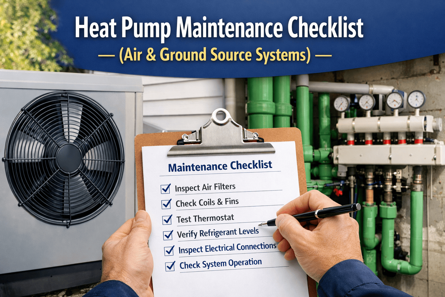
Heat Pump Maintenance: Air-Source, Ground-Source, and Water-Source Systems

By James smith on April 4, 2026

heat-pump-maintenance-air-source-ground-source-water-source

Heat pump adoption in commercial facilities accelerated faster in 2024–2026 than most maintenance teams prepared for. Facilities departments that have spent decades maintaining gas-fired heating and split DX cooling systems are now managing air-source heat pumps operating at 0°F, geothermal ground loops that haven't been accessed since installation, and water-source heat pump networks where the loop chemistry determines whether every unit on the circuit heats efficiently or struggles. The maintenance requirements differ materially by heat pump type — and the most common maintenance failure is applying an air-source PM template to a ground-source or water-source system that has entirely different critical components, failure modes, and inspection intervals. Sign in to OxMaint to configure type-specific heat pump PM templates for your asset fleet — or book a demo to see heat pump maintenance tracking configured for each system type in your facility.

Why Maintenance Matters

What Missed Heat Pump Maintenance Actually Costs

30–50%
Efficiency loss from a frosted-over outdoor coil vs. a clear coil — defrost cycle maintenance directly determines winter heating efficiency
3–4×
Heat energy delivered per unit of electricity consumed by a well-maintained heat pump — degraded refrigerant charge or fouled coils reduce this to 1.5–2× or worse
20–30 yrs
Design lifespan of ground-source heat pump loop infrastructure — loop failures from poor water chemistry cut this to 8–12 years in some installations
32°F
Below this, water-source loop temperature requires boiler supplementation — loop chemistry failures cause freeze damage that destroys the entire loop field
System Types

Three Heat Pump Types — What Makes Each Maintenance Different

The reversing valve, compressor, and refrigerant circuit are common to all heat pump types and require similar maintenance. What differs significantly is the heat source/sink interface — the component that exchanges heat with the environment. That interface determines the critical failure modes and maintenance priorities specific to each type. Sign in to OxMaint to configure separate PM templates per heat pump type across your asset fleet.

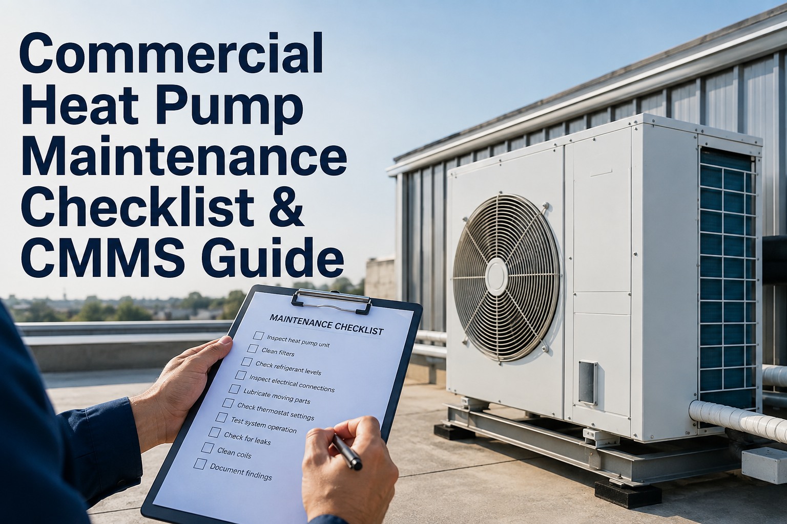
Air-Source
Air-to-Air and Air-to-Water Heat Pumps
Extracts heat from outdoor air through the outdoor coil. The heat source interface is the outdoor coil — directly exposed to weather, debris, insects, and seasonal temperature extremes. The most widely deployed type; most subject to airflow restriction failures from coil fouling and defrost cycle failures from sensor degradation.
Critical maintenance items
Outdoor coil cleaning — fouling reduces heat transfer and forces compressor to work harder
Defrost cycle verification — sensor failure causes continuous icing or failure to defrost
Reversing valve operation — stuck valve leaves system in one mode permanently
Refrigerant charge check — low charge causes compressor overheating and efficiency loss
Crankcase heater operation — failure causes refrigerant migration into compressor overnight
Primary failure risk: Outdoor coil icing from defrost cycle failure; reversing valve seizure in one mode; refrigerant migration from crankcase heater failure in cold climates.
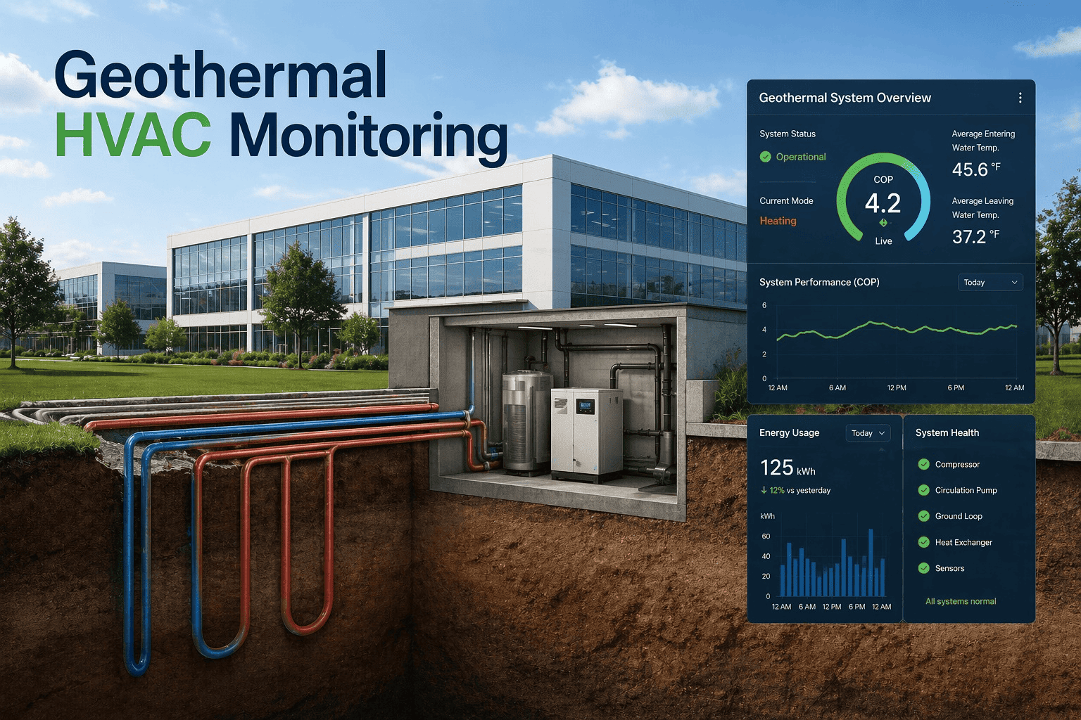
Ground-Source
Geothermal / Ground-Coupled Heat Pumps
Extracts heat from the ground through buried loop piping filled with water or antifreeze. The heat source interface is the ground loop — mostly inaccessible once buried but subject to fluid chemistry degradation, flow rate changes, and antifreeze concentration decline. Indoor units are protected from outdoor conditions and require less maintenance than air-source units.
Critical maintenance items
Ground loop fluid chemistry — pH, inhibitor concentration, antifreeze level checked annually
Loop flow rate verification — reduced flow indicates air lock, pump degradation, or fouling
Entering/leaving water temperature measurement — confirms ground thermal capacity is adequate
Antifreeze concentration — must remain below freeze point of coldest expected ground temperature
Expansion tank and pressure vessel — ground loop pressure must remain positive at all points
Primary failure risk: Loop fluid chemistry degradation causing corrosion in headers and heat exchangers; antifreeze dilution from makeup water additions causing freeze damage; loop pump failure.
Water-Source
Closed-Loop Water-Source Heat Pumps
Multiple units connected to a common water loop maintained between 60°F and 90°F by a cooling tower (summer) and boiler (winter). Individual units reject or absorb heat from the loop — units in interior zones may be cooling while perimeter units heat simultaneously. The loop and its ancillary equipment require separate maintenance from the individual water-source units.
Critical maintenance items
Loop water temperature range — must stay 60–90°F; outside range reduces efficiency, may damage units
Loop water chemistry — scale, corrosion, and biological growth control per water treatment programme
Cooling tower and boiler PM — the loop temperature management equipment that serves all units
Individual unit coaxial coil cleaning — water-to-refrigerant heat exchanger fouling is the primary unit-level failure
Loop pump operation and impeller condition — inadequate flow starves all units simultaneously
Primary failure risk: Loop temperature outside 60–90°F range from cooling tower or boiler failure affecting all units simultaneously; coaxial coil fouling from scale or biological growth in individual units.
One Template Cannot Maintain Three Different Heat Pump Types. OxMaint Configures One for Each.
Air-source, ground-source, and water-source heat pumps share a refrigerant circuit and a reversing valve — and diverge on everything else. OxMaint configures type-specific PM templates with the correct tasks, intervals, and inspection points for each system in your portfolio.
Critical Monitoring Points

Key Inspection Points by Component — All Heat Pump Types

These components are common to all heat pump types and require inspection at defined intervals regardless of heat source configuration. Type-specific additional tasks are listed in the PM schedule section. Sign in to OxMaint to configure monitoring templates with mandatory sign-off per component and automatic scheduling.

RVL
Reversing Valve

The reversing valve shifts refrigerant flow direction to switch between heating and cooling modes. A faulty valve leaves the system permanently in one mode — one of the most common heat pump service calls. The valve itself rarely fails mechanically; the solenoid that activates it is the more common failure point.

Inspection Points
Mode switching test — initiate changeover from heating to cooling and back
Solenoid continuity check — measure coil resistance against specification
Valve body for refrigerant bypass — hissing at valve in either mode indicates internal leak
Switching temperature differential — confirm mode change occurs at correct setpoint
Failure indicators
System stuck in cooling in winter or heating in summer
Slow mode switching causing temperature overshoot in either direction
DFR
Defrost Cycle (Air-Source)

Air-source heat pumps initiate a defrost cycle when the outdoor coil temperature falls to approximately 26°F — reversing refrigerant flow to melt ice. The system returns to heating when the coil reaches ~58°F. Normal defrost cycles last 5–15 minutes. A system that never defrosts or defrosts constantly requires immediate service.

Inspection Points
Defrost initiation — coil temperature sensor triggers within specification
Defrost termination — cycle ends when coil reaches ~58°F, not just timer expiry
Outdoor fan pauses during defrost — fan running during defrost inhibits ice melt
Backup heat stages during defrost — prevents cold air from being circulated indoors
Failure indicators
Never defrosting — sensor failure or reversing valve issue; unit will ice over
Constant defrost — low refrigerant or dirty coil; unit cannot heat effectively
CMP
Compressor

The compressor is the highest-value component in any heat pump — replacement cost can exceed 50% of total unit value. Compressor failures are usually preceded by detectable warning signs: elevated discharge temperature, abnormal current draw, or refrigerant charge deviation. Catching these early converts a compressor replacement into a refrigerant recharge or reversing valve repair.

Inspection Points
Compressor amp draw — compare against nameplate; high amps indicate mechanical distress
Discharge and suction pressures — compare against operating temperature superheat/subcooling targets
Discharge line temperature — elevated temperature indicates refrigerant issues or valve problems
Crankcase heater operation (cold climates) — failure causes refrigerant migration and liquid floodback
Failure indicators
High amp draw with correct refrigerant charge — internal mechanical wear
Liquid floodback on startup — crankcase heater failure; can hydrolock compressor
REF
Refrigerant Charge

Heat pump refrigerant charge must be verified in both heating and cooling mode — the correct charge produces different pressure readings in each mode. Low refrigerant charge degrades efficiency before it stops the unit from operating. A 10% undercharge can reduce heating capacity by 20% and COP by 15% without triggering any fault code.

Inspection Points
Suction and discharge pressure — verify against manufacturer's charging charts for current outdoor/indoor temperature
Superheat (cooling mode) and subcooling (heating mode) — both modes must be checked
Refrigerant type verification — critical now that R-410A equipment and R-32/R-454B equipment coexist
Visual leak check — all fittings, valve stems, flare connections, and service ports
Failure indicators
Low suction pressure with high superheat — refrigerant undercharge or TXV restriction
High suction pressure with low superheat — refrigerant overcharge or reversing valve bypass
COL
Coil Condition (Air-Source)

Both the outdoor (source) coil and indoor (distribution) coil require cleaning on different intervals. The outdoor coil is exposed to weather, pollen, insects, and airborne debris — fouling restricts airflow and forces the compressor to work against elevated head pressure. The indoor coil accumulates dust and biological growth when drain pans are not maintained.

Inspection Points
Outdoor coil fin condition — check for debris, fin damage, and corrosion
Coil foam-clean with coil cleaner — at least annually; twice yearly in high-debris environments
Fin straightening — bent fins restrict airflow more than debris in many field installations
Condensate drain pan and drain — algae blockage causes pan overflow and indoor damage
Failure indicators
High head pressure in cooling — outdoor coil fouled, airflow restricted
Low suction pressure in heating — outdoor coil airflow restricted, less heat transfer
LOP
Loop / Water Circuit (Ground & Water-Source)

Ground-source and water-source heat pumps require maintenance of the water circuit that no air-source PM template addresses. Loop chemistry, antifreeze concentration, and flow rate are the parameters that determine whether the ground or building loop can transfer heat at the rate the heat pump requires. Sign in to log loop chemistry readings in OxMaint.

Inspection Points
Loop fluid pH — target 8.0–9.0 for corrosion inhibition; outside range requires treatment
Antifreeze concentration — freeze protection must cover coldest expected ground or outdoor temperature
Entering and leaving water temperature — confirm loop is providing adequate heat exchange
Loop flow rate and pump pressure differential — reduced flow indicates air lock, fouling, or pump wear
Failure indicators
Entering water temperature out of 60–90°F range for WSHP — boiler or cooling tower issue
Antifreeze below freeze-point threshold — immediate risk of loop freeze and pipe rupture
PM Schedule

Heat Pump Preventive Maintenance by Frequency and Type

Heat pump PM is structured across seasonal and calendar-based intervals that align with the heating-dominant and cooling-dominant operating modes. The most important windows are the pre-season checks — before the first heating demand of autumn and before peak cooling demand in spring — when defrost systems, reversing valves, and refrigerant charge can be verified without weather pressure. Book a demo to see seasonal heat pump PM templates pre-configured in OxMaint for each system type.

Spring
Pre-Cooling Season
Outdoor coil cleaning (air-source) — foam-clean coil and straighten fins after winter. Confirm 12–24" clearance at coil intake and 36"+ at discharge fan. Remove debris accumulated over winter. Inspect base pan and drain for corrosion or blockage.
Reversing valve mode-change test — initiate switchover from heating to cooling mode. Confirm clean transition, correct supply air temperature after mode change, and solenoid response within specification.
Refrigerant charge verification in cooling mode — measure suction and discharge pressures, subcooling, and superheat. Verify against manufacturer's charging chart for current ambient conditions. Log results in OxMaint against the unit asset record.
Loop chemistry check (ground / water-source) — sample loop fluid, test pH, inhibitor concentration, and antifreeze level. Adjust treatment before cooling season demand peaks. For WSHP, verify cooling tower is operational and loop temperature below 90°F. Log chemistry results in OxMaint.
Autumn
Pre-Heating Season
Defrost cycle verification (air-source) — simulate low coil temperature and verify defrost initiation. Confirm reversing valve shifts to defrost mode, outdoor fan pauses, backup heat stages on, and cycle terminates when coil reaches ~58°F. Set balance point and lockout temperatures appropriate for local climate. Book a demo to configure defrost test PM in OxMaint.
Crankcase heater verification (cold climates) — confirm crankcase heater is energised before first cold snap. A failed crankcase heater allows refrigerant to migrate into the compressor oil overnight — startup then causes liquid floodback that can hydraulically lock and destroy the compressor within seconds.
Antifreeze concentration check (ground-source) — antifreeze concentration must be confirmed before the first sustained cold period. Adding makeup water during the season can dilute antifreeze below the freeze point. Verify concentration covers the coldest expected ground temperature plus a 10°F safety margin.
Backup heat verification — confirm auxiliary electric resistance strips or gas backup are operational and staging correctly. In cold climates, backup heat is the safety net when the heat pump cannot maintain setpoint — a failed backup heat element is not discovered until a prolonged cold snap.
ANN
Annual
Full refrigerant circuit assessment — both modes. Compressor amp draw, discharge line temperature, suction and discharge pressures, superheat and subcooling in both heating and cooling mode. Visual leak check of all fittings, flares, and service ports. Results logged in OxMaint per unit with comparison to prior year readings. Sign in to track refrigerant records per heat pump asset.
Ground loop comprehensive inspection (ground-source) — full chemistry analysis including pH, dissolved oxygen, inhibitor package, bacterial count, and antifreeze concentration. Flow rate measurement. Expansion tank pre-charge pressure check. Loop pressure verified positive at highest point in the system. Any chemistry exceedance requires loop flush and recharge.
Coaxial coil descaling (water-source) — water-to-refrigerant coaxial coils are susceptible to scale accumulation from loop water minerals. Annual chemical descaling of coaxial coils maintains heat transfer efficiency. Neglected descaling causes progressive capacity reduction that is not detected until the unit fails to maintain setpoint. Book a demo to configure annual descaling PM triggers in OxMaint.
Electrical connection inspection — torque all terminal connections per manufacturer specifications. Measure capacitor capacitance — start and run capacitors degrade before they fail completely, causing hard starts that overstress compressors. Measure motor current on all fan motors and compressor. Replace capacitors showing more than 10% capacitance loss.

What Heat Pump Service Engineers Say About Maintenance Programmes

"
The most common mistake I see facilities teams make with heat pump fleets is running a single generic HVAC PM template across air-source, ground-source, and water-source units simultaneously. The reversing valve and compressor checks apply to all of them. The defrost cycle verification only applies to air-source. The loop chemistry check only applies to ground and water-source. The coaxial coil descaling only applies to water-source. When you run a generic template, you are performing unnecessary checks on some units and completely missing the critical checks on others. An air-source unit that has never had its crankcase heater verified in a cold climate will eventually fail its compressor on a January morning. A water-source unit that has never had its coaxial coil descaled will lose 25% of its rated capacity over five years and the occupants will think the units are undersized. Type-specific PM templates — configured in the CMMS per unit type and executed consistently — are the single most impactful change most facilities teams can make to their heat pump programme.
OxMaint Heat Pump Capabilities

What OxMaint Delivers for Heat Pump Fleet Maintenance

Templates
Type-Specific PM Templates
Separate PM templates per heat pump type — air-source, ground-source, water-source — each with the correct task lists, seasonal triggers, and inspection points for that system. No single generic template applied to all three types simultaneously. Sign in to configure type-specific PM templates.
Seasonal
Spring and Autumn Pre-Season PM
Pre-cooling and pre-heating season PM work orders generated automatically before each seasonal transition — defrost verification in autumn, refrigerant charge in spring, loop chemistry before both seasons. PM scheduled during off-peak periods when technicians have better availability and weather conditions allow full-length tests. Book a demo to configure seasonal PM scheduling.
Refrigerant
Per-Unit Refrigerant Records
Every refrigerant check, charge adjustment, and leak inspection linked to the specific heat pump asset record — with refrigerant type, amount, technician certification, and annual leak rate calculation. EPA Section 608 compliance records maintained automatically at each service event for applicable units.
Loop
Ground and Water Loop Chemistry Tracking
Ground-source loop chemistry readings — pH, antifreeze concentration, inhibitor level — logged against the loop asset record with trend analysis and out-of-specification alerts. WSHP loop temperature records linked to cooling tower and boiler asset records. Sign in to configure loop monitoring records.
Defrost
Defrost Cycle Test Records
Defrost cycle verification PM — test initiation, termination, outdoor fan pause, backup heat staging — logged per air-source unit with dated technician sign-off. Pre-autumn seasonal defrost PM auto-generated for all air-source assets before first cold season operation.
Fleet
Multi-Type Fleet Dashboard
All heat pump types visible on a single compliance dashboard — PM completion by type, overdue inspection alerts, refrigerant record currency, and loop chemistry status — across all assets in the portfolio. No separate tracking for each system type. Book a demo to see fleet dashboard configured for mixed heat pump portfolios.
Air-Source, Ground-Source, Water-Source — One Platform, Three Correct PM Programmes.
OxMaint configures type-specific PM templates, seasonal scheduling, refrigerant records, and loop chemistry tracking for every heat pump type in your facility fleet. Free trial — no implementation fees.
Common Questions

Facilities Managers Ask These About Heat Pump Maintenance

Why does the outdoor unit steam or smoke during winter operation?
Steam from the outdoor unit during winter indicates the defrost cycle is operating correctly — the heat pump has reversed into cooling mode to melt ice from the outdoor coil, and the steam is water vapour from melting ice. Normal defrost cycles last 5–15 minutes. Frequent defrost cycles (every 30–45 minutes) in cold humid conditions are also normal. If the unit appears to be defrosting constantly or never defrosting, that indicates a defrost sensor or reversing valve issue requiring service. Sign in to log defrost cycle test results in OxMaint for each air-source unit in your fleet.
How often should ground-source loop fluid chemistry be tested?
Annual testing is the minimum for established ground-source installations. Pre-season testing before each winter heating season is recommended — antifreeze concentration must be confirmed before the first sustained cold period, as makeup water additions during the season can dilute antifreeze below the freeze point. Any change in loop flow rate or entering water temperature should trigger an unscheduled chemistry test — these are leading indicators of chemistry degradation or contamination. Book a demo to see loop chemistry PM scheduling in OxMaint.
What causes a heat pump to get stuck in cooling mode in winter?
A heat pump stuck in cooling mode in winter is almost always a reversing valve failure — specifically, the solenoid that controls valve position has failed to energise or de-energise correctly. The valve body itself rarely fails mechanically. Reversing valve solenoid failure is the most common cause of mode-stuck heat pumps and is a straightforward repair for a qualified technician. Never defrosting — a different problem from mode-stuck — usually indicates a defrost sensor failure or a low-refrigerant condition preventing the coil from reaching defrost initiation temperature. Sign in to log reversing valve test results per unit in OxMaint.
What loop temperature range must water-source heat pumps operate within?
Water-source heat pumps are designed to operate with entering loop water between 60°F and 90°F. Below 60°F, the refrigerant circuit cannot absorb adequate heat from the loop in heating mode — efficiency drops and compressor protection may shut the unit down. Above 90°F, the unit cannot reject heat to the loop in cooling mode — efficiency drops and high-pressure safety cutouts may activate. Loop temperature is maintained by the cooling tower (summer) and supplemental boiler (winter). Both require their own independent PM programmes separate from the individual WSHP units. Book a demo to see WSHP loop temperature tracking and boiler/cooling tower PM integration in OxMaint.

Share This Story, Choose Your Platform!