Dynamic Balancing of Rotating Equipment in Manufacturing
By Alex Rowan on July 17, 2026
Dynamic imbalance drives roughly 40% of all vibration-related failures in manufacturing rotating equipment, making it the single most preventable cause of premature bearing, seal, and coupling wear on the plant floor. Left unresolved, even a small mass offset accelerates fatigue across the entire drivetrain and turns a routine $400 balance job into a multi-thousand-dollar shop repair. This guide walks through imbalance detection, single-plane and two-plane field balancing procedures, ISO 1940 balance grade tolerances, and how to schedule recurring balance checks inside your CMMS after every major repair. Ready to operationalize it across your plant? Start Free Trial and build your balancing workflows today.
FIELD BALANCING PLAYBOOK
What if 70% of your rotor vibration could be eliminated in a single afternoon?
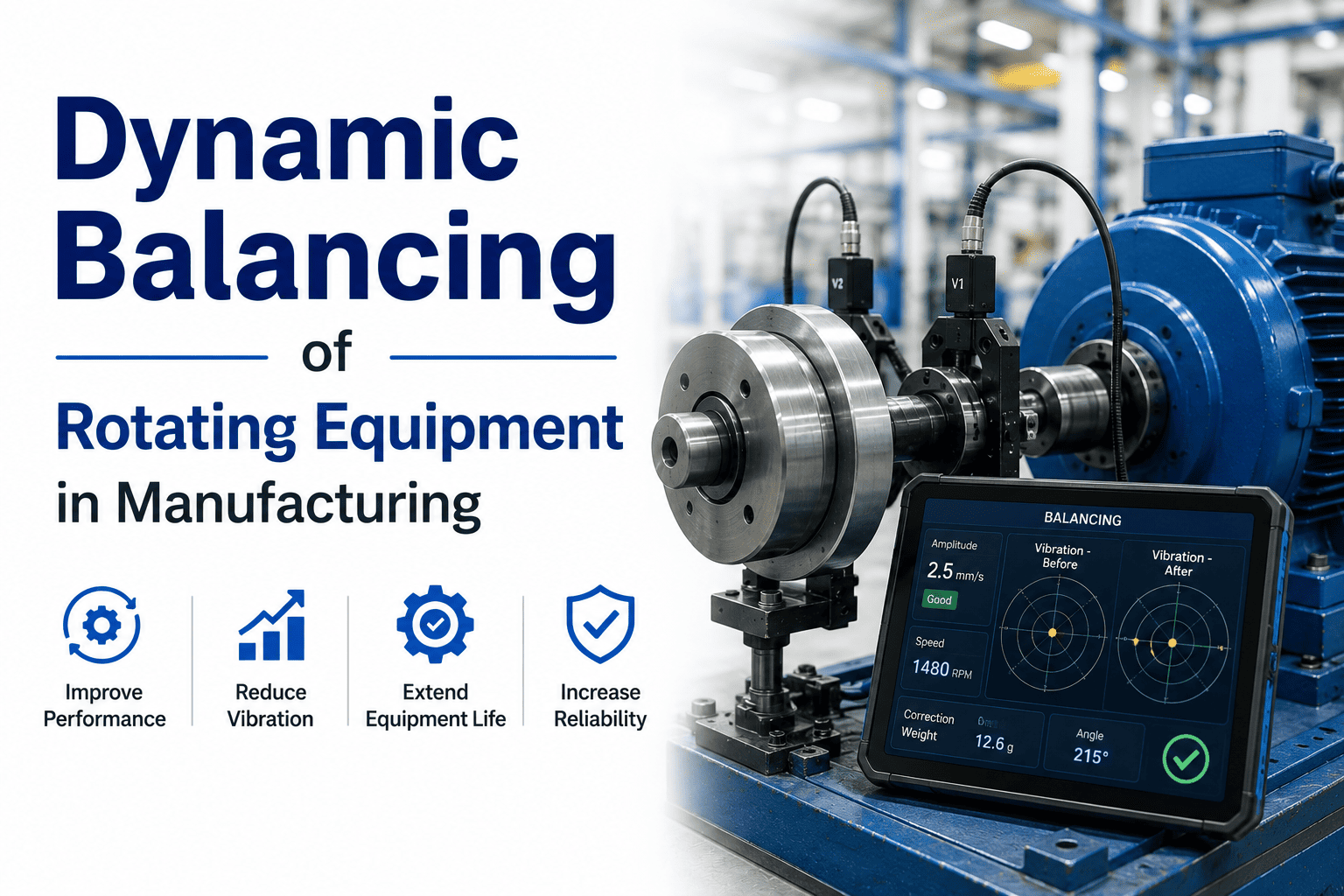
Dynamic imbalance is the leading root cause of vibration in manufacturing rotating equipment — and field balancing resolves it without pulling the rotor for costly shop work. This guide shows you exactly how to detect, correct, and schedule balance checks inside your CMMS after every major repair.
OF ROTOR VIBRATION CASES TRACE BACK TO MASS IMBALANCE — CORRECTABLE IN-FIELD WITH A VIBRATION ANALYZER AND TRIAL WEIGHTS
THE COST OF IMBALANCE
Why imbalance quietly drains maintenance budgets
A rotor running 0.5 oz·in out of balance at 3,600 RPM generates centrifugal forces that travel bearing-to-bearing-to-foundation — every revolution, every minute, every shift. The damage is cumulative, invisible until it isn't, and almost always avoidable.
40%
OF VIBRATION-RELATED MACHINE FAILURES ARE ROOTED IN ROTOR IMBALANCE
50%
REDUCTION IN BEARING LIFE FOR EVERY DOUBLING OF VIBRATION VELOCITY BEYOND ISO 10816 LIMITS
$8K
AVERAGE SHOP REPAIR BILL AVOIDED BY CATCHING IMBALANCE EARLY WITH FIELD BALANCING
6×
HIGHER MAINTENANCE COST WHEN A BALANCE ISSUE ESCALATES TO COUPLING, SEAL AND HOUSING DAMAGE
WORKED EXAMPLE
A 180-asset motor repair plant was spending roughly $42,000 per year on emergency rebuilds tied to recurrent vibration alarms. After instituting quarterly field-balancing checks and logging trial-weight runs inside their CMMS, vibration-related rebuilds dropped 63% in the first twelve months — freeing over $26K for predictive work instead of reactive firefighting. The material cost per balance correction averaged $14 in washers and weights.
DETECTION CHECKLIST
Spotting imbalance before it becomes a rebuild
Vibration at 1× running speed is the classic signature of imbalance — but confirming it requires reading amplitude, phase, and the effect of a trial weight. Use this checklist to verify imbalance is the true root cause before reaching for correction weights.
1× RPM amplitude dominance
Vibration spectrum shows a clear peak at 1× running speed with minimal 2× or sub-synchronous content.
Radial vs axial ratio
Radial vibration in horizontal and vertical directions is significantly higher than axial — typically 3:1 or greater.
Phase stability across readings
Phase angle between horizontal and vertical radial probes differs by roughly 90° and stays repeatable run-to-run.
ISO 10816 alarm exceeded
Overall vibration velocity exceeds the ISO 10816 zone boundary (typically 2.8 mm/s RMS for flexible-mounted machines).
Trial-weight response
Adding a known trial weight produces a measurable, proportional change in both amplitude and phase — confirming sensitivity.
Rule out misalignment & looseness
2× peak is minor, no sub-synchronous components, and phase across the coupling is stable — isolating imbalance as the cause.
FIELD BALANCING PROCEDURE
A step-by-step timeline for in-place correction
Field balancing follows a disciplined four-step sequence: baseline, trial weight, calculate, correct. Each step's output feeds directly into the next, and every run should be logged in your CMMS for audit traceability.
01
Baseline run & reference mark
Mount the accelerometer on the bearing housing nearest the imbalance, attach a reflective tape to the shaft, and run the machine at operating speed. Record initial amplitude (mm/s) and phase (degrees). This is your unbalance vector — the reference every calculation returns to.
02
Trial weight application
Attach a known trial weight (typically 5–30 g depending on rotor mass and radius) at a measured angle from the reference mark. Re-run the machine and record the new amplitude and phase. The shift between baseline and trial vectors reveals the influence coefficient — how much correction each gram provides.
03
Calculate correction mass & angle
Using vector math or a balancing calculator, solve for the correction weight magnitude and angular position that brings the residual vibration inside tolerance. Most modern analyzers compute this automatically; manual vector diagrams still work for field crews without software.
04
Apply, verify & document
Install the calculated correction weight, re-run, and confirm residual vibration is within ISO 1940 G-grade tolerance for the rotor class. Log the trial-weight runs, final correction, and residual amplitude in your CMMS work order so the asset's balance history is auditable.
SINGLE-PLANE INFLUENCE COEFFICIENT
Wc = −Wt × (V0 ÷ ΔV)
Wc = correction weight · Wt = trial weight · V0 = original vibration vector · ΔV = vibration change from trial weight. Best for narrow rotors (D/L ratio over 1) under 1,000 RPM where couple imbalance is negligible.
TWO-PLANE CORRECTION
[WA, WB] = −[IC]−1 × [VA, VB]
Two trial runs (one per plane) build a 2×2 influence-coefficient matrix. Required for rotors with L/D over 0.5 or any machine above 1,800 RPM, where dynamic (couple) imbalance cannot be resolved from a single plane.
BALANCING TOLERANCES
ISO 1940 balance grades — what "good enough" really means
ISO 1940-1 defines balance quality grades (G-grades) that set the permissible residual specific unbalance for each rotor class. Hitting the right grade protects bearings without over-spending on unnecessary precision.
BALANCE GRADE
PERMISSIBLE RESIDUAL (e·ω)
TYPICAL ROTOR TYPE
EXAMPLE AT 1,500 RPM
G 1.0
1.0 mm/s
Precision spindles, gyroscopes, small high-speed armatures
≤ 6.4 μm
G 2.5
2.5 mm/s
Gas turbines, steam turbines, turbo-compressors, medium electric motors
≤ 16 μm
G 6.3
6.3 mm/s
Process pumps, fans, blowers, general-purpose motors (most common plant target)
Plant-floor rule of thumb: G 6.3 satisfies roughly 80% of general manufacturing rotating equipment. Only specify tighter grades (G 2.5 or better) for machines running above 3,600 RPM, with sleeve bearings, or in vibration-sensitive service — tighter tolerances cost 2–3× more shop time per rotor.
Turn balancing from a fire drill into a scheduled workflow
Oxmaint auto-generates balance-check work orders after every major repair and logs trial-weight runs, residual amplitudes, and ISO grade compliance against each asset — so nothing slips through the cracks.
Scheduling balance checks after every major repair
The single most overlooked step in field balancing is the follow-up. Without a CMMS trigger, the next imbalance creeps back unchecked for months. Tie balance verification to post-repair work orders and quarterly condition routes.
TRIGGER 1
Post-repair verification
Auto-create a balance-check sub-task inside any work order flagged "major repair" — bearing replacement, rotor swap, coupling change, or impeller trim. The technician logs baseline, trial, and residual readings directly in the work order before closing it.
TRIGGER 2
Condition-based routes
Schedule a vibration route every 90 days for critical assets (ISO 10816 Zone B or higher). When 1× amplitude trends upward by 25%, the CMMS auto-generates a balance-check work order with the last known correction weights attached.
TRIGGER 3
Annual audit trail
Each balance correction logs rotor ID, grade achieved, technician, weights applied, and residual amplitude. The audit trail satisfies ISO 55000 asset-management requirements and gives reliability engineers a per-asset balance history for failure analysis.
"
We went from six emergency rotor rebuilds a year down to one — purely by making balance checks a non-negotiable step in every post-repair work order. The CMMS forces it; nobody skips it.
How do I know if I need single-plane or two-plane balancing?
Use single-plane for narrow rotors where length-to-diameter ratio is under 0.5 and running speed is below 1,000 RPM — typical for fans, flywheels, and thin impellers. Switch to two-plane for longer rotors (L/D over 0.5), any machine above 1,800 RPM, or when the two bearing housings show noticeably different vibration amplitudes. Two-plane resolves both static and couple imbalance; single-plane only corrects static.
What ISO balance grade should my plant target?
G 6.3 covers about 80% of general manufacturing rotating equipment — process pumps, fans, blowers, and standard motors. Specify G 2.5 for turbines, high-speed compressors, and sleeve-bearing machines. Over-specifying wastes shop time: pushing a G 6.3 fan to G 1.0 can triple balancing cost with no measurable reliability gain. Always tie the target grade to the asset's criticality and running speed in your CMMS asset record.
Can field balancing replace shop balancing entirely?
Field balancing corrects residual imbalance introduced by wear, deposits, or minor repairs — but it cannot fix a rotor with structural distortion, cracked shafts, or severely damaged journals. Those require shop balancing on a balancing machine. Field balancing is the right tool for maintenance correction; shop balancing is for manufacture and major overhaul. Book a Demo to see how Oxmaint tracks which path each asset needs.
How often should balance checks be scheduled in the CMMS?
Tie a balance verification to every major repair work order (bearing swap, rotor change, coupling replacement) as a mandatory close-out step. For critical assets, add a condition-based vibration route every 90 days — when 1× amplitude rises 25% above baseline, auto-trigger a balance check. Annual full balance audits suit lower-criticality machines. The key is making the trigger automatic, not relying on someone to remember.
What equipment do I need to field-balance a rotor?
A vibration analyzer with phase capability (laser tachometer or optical pickup), an accelerometer rated for the machine's frequency range, a set of calibrated trial weights and clamps, and a reference mark on the shaft. Modern two-channel analyzers compute influence coefficients and correction vectors automatically — but the same four-step procedure (baseline, trial, calculate, correct) works with a single-channel meter and manual vector diagrams if that's what your crew has. Start Free Trial to log every run inside your CMMS.
Stop letting imbalance eat your bearings
Deploy structured field-balancing workflows across every rotating asset — with CMMS-tracked trial weights, ISO grade compliance, and post-repair verification built in.





![equipment-asset-register-template-for-manufacturing-plants-[free-excel]](./manage-post-2k26/uploads/equipment-asset-register-template-for-manufacturing-plants-[free-excel].png)