Between 5 and 10 arc flash incidents occur every single day in the United States — and the total financial impact of a single event can reach up to $15 million when you account for medical costs, equipment replacement, legal liability, and lost production. A structured electrical panel and power distribution maintenance program is the most direct way to prevent that outcome: the 2023 NFPA 70B standard has now made annual infrared thermography inspections of all electrical equipment mandatory, shifting electrical maintenance from a recommended practice to an enforceable compliance obligation. This complete checklist covers every critical inspection point — from daily panel walk-arounds through annual thermal imaging and breaker testing — giving your electrical maintenance team the framework to protect people, protect assets, and keep your facility compliant with confidence.
Inspection, Safety & Compliance Guide
Electrical Panel & Power Distribution Maintenance Checklist
Panel Inspection · Thermal Imaging · Breaker Testing · Grounding · Arc Flash Compliance
NFPA 70B 2023
NFPA 70E
Safety & Regulatory Compliance
5–10
Arc flash incidents per day in the United States
$15M
Maximum total financial impact per single arc flash incident
400
Fatalities from electrical incidents annually in the U.S.
12 mo.
Maximum interval for IR thermography — now mandatory under NFPA 70B 2023
The Four Failure Modes That Take Down Power Distribution Systems
Every electrical panel failure or arc flash incident traces back to one of four root causes. Understanding the failure mode — not just the symptom — is what turns a generic inspection into a precision reliability tool. Each cause has a specific countermeasure, and each countermeasure maps directly to a checklist item.
Cause 01
Loose & Degraded Connections
Thermal cycling causes connection hardware to expand and contract with every load cycle. Over years, this loosens terminations, increases contact resistance, and generates heat that degrades insulation — all before any fault code appears on a panel.
Countermeasure: Quarterly torque verification + annual infrared thermal scan under full load
Cause 02
Insulation Breakdown
Moisture ingress, chemical contamination, and age silently degrade cable and busbar insulation. A conductor that tests fine at commissioning may have insulation resistance below safe thresholds years later — invisible without a megohmmeter test.
Countermeasure: Annual insulation resistance testing with trending against prior-year baseline
Cause 03
Breaker Degradation
Circuit breakers that are never operated under load develop mechanical stiffness and contact oxidation. A breaker that fails to trip on overcurrent doesn't just damage equipment — it removes the last line of protection before a catastrophic fault.
Countermeasure: Annual trip-function testing and operation under load to verify responsiveness
Cause 04
Grounding System Failure
Grounding connections corrode, ground conductors are inadvertently disconnected during work, and resistance climbs above safe limits. Poor grounding means a fault has no safe return path — increasing the probability and severity of any arc event.
Countermeasure: Monthly grounding continuity check + annual ground resistance testing below 1 ohm
Schedule Electrical PM Automatically — With Full Audit Trail
OxMaint auto-schedules electrical panel inspections by calendar interval or equipment condition, delivers digital checklists to technician devices, and captures every test result in a compliance-ready audit trail — aligned with NFPA 70B documentation requirements.
Electrical Panel & Power Distribution Maintenance Checklist
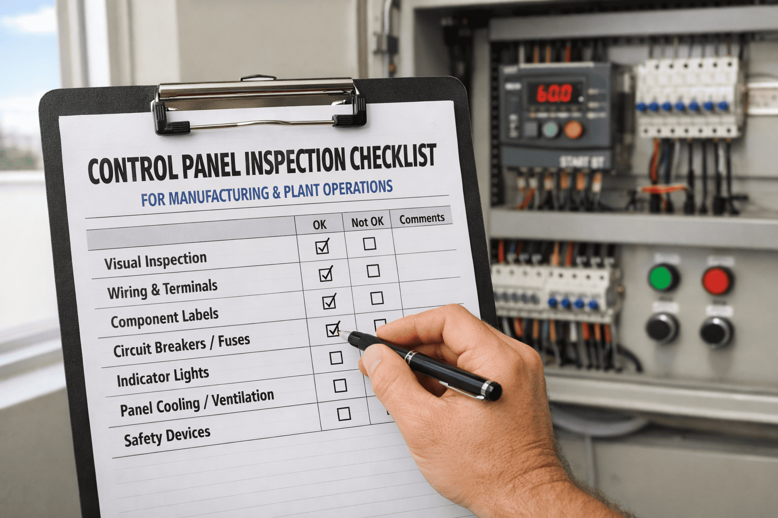
Electrical maintenance runs across four inspection frequencies — monthly visual checks, quarterly electrical testing, annual diagnostic surveys, and every-5-year system studies. Each interval is designed to catch what the others miss. The 2023 NFPA 70B standard now specifies mandatory intervals for key tasks; facilities that skip any level create a compliance gap that OSHA can reference under the General Duty Clause in the event of an incident.
Monthly
Visual Inspection & Safety Verification
20–30 minutes per panel · Qualified technician · LOTO procedures required before opening
Panel Exterior & Environment
Inspect panel enclosure exterior for physical damage, corrosion, paint discoloration, or heat staining — any discoloration on the enclosure face is a thermal warning requiring immediate investigation
Verify panel enclosure is properly sealed and doors close fully — gaps allow moisture ingress and contamination that degrades insulation and accelerates corrosion on busbars and terminals
Confirm panel area is free from stored materials within required clearance distance — NFPA 70E requires minimum 36 inches of clear working space in front of panels rated 600V and below
Check ambient temperature and ventilation in the electrical room — panel rooms exceeding rated ambient temperature accelerate insulation aging and component degradation
Verify arc flash hazard labels are present, legible, and current on all panels — missing or outdated labels are a direct NFPA 70E compliance violation and create incident liability
Panel Interior & Labeling
Confirm all circuit breakers and fuses are correctly labeled and that panel directory matches actual circuit assignments — unlabeled or mislabeled circuits create life-threatening delays during emergencies
Inspect for visible signs of overheating — burned insulation odor, discolored wiring, carbon deposits, or melted plastic around breaker terminations are immediate action items
Check for moisture, condensation, or corrosion on busbars, neutral bars, and terminal blocks — surface oxidation on busbar contacts increases resistance and is a precursor to thermal failure
Verify no open knockouts or penetrations in the panel enclosure — unsealed entries provide a path for insects, rodents, and moisture that have caused multiple documented arc flash events
Confirm grounding conductor is visibly present and connected at the panel — a disconnected ground conductor may not produce any fault condition until a downstream event occurs
Quarterly
Electrical Testing & Connection Verification
60–90 minutes per panel · Calibrated instruments required · LOTO mandatory
Load & Voltage
Measure voltage at all three phases and verify within ±10% of rated voltage — phase imbalance above 2% causes motor overheating and accelerates winding insulation degradation across connected loads
Record current on each phase and compare against rated capacity — circuits operating above 80% of rated ampacity consistently are candidates for load redistribution before a thermal event occurs
Verify load balance across all phases — unbalanced loading increases neutral current, which can exceed neutral conductor ratings in systems with significant harmonic loads
Confirm power factor is within acceptable range — low power factor indicates reactive load imbalance and increases conductor heating beyond what amperage readings alone suggest
Connections & Terminations
Perform torque verification on all power-carrying connections using a calibrated torque wrench and OEM-specified torque values — never re-torque energized connections; follow LOTO procedures before beginning
Inspect all wire terminations for signs of heat damage, conductor strand breakage, or insulation creep — terminations that show copper discoloration have already experienced elevated resistance heating
Verify busbar connection hardware is tight and contact surfaces are clean — dust and oxidation on busbar contact faces increase resistance; clean with dry cloth or appropriate contact cleaner only
Check surge protective device (SPD) status indicators if installed — many SPDs provide a visual indicator when the device has been stressed by a transient and requires replacement
Grounding & Protection
Verify grounding continuity using a calibrated resistance tester — grounding resistance must measure below 1 ohm; values above this threshold indicate corrosion, a broken conductor, or an improper connection requiring repair
Inspect bonding between neutral and ground at the service entrance panel — the neutral-to-ground bond must exist at only one point in the system; multiple bonds create circulating ground currents and shock hazards
Verify ground fault circuit interrupter (GFCI) protection is functioning — test each GFCI outlet and breaker using the test button; a device that does not trip is non-functional and must be replaced immediately
Check overload relay settings against connected motor nameplate full load amps — incorrect settings remove thermal protection and can allow motors to overheat without triggering protective shutdown
Annual
Full Diagnostic Survey — NFPA 70B Mandatory Interval
Thermal camera · Megohmmeter · Breaker test set · Qualified electrical professional
Infrared Thermography & Insulation Testing
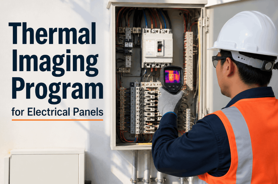
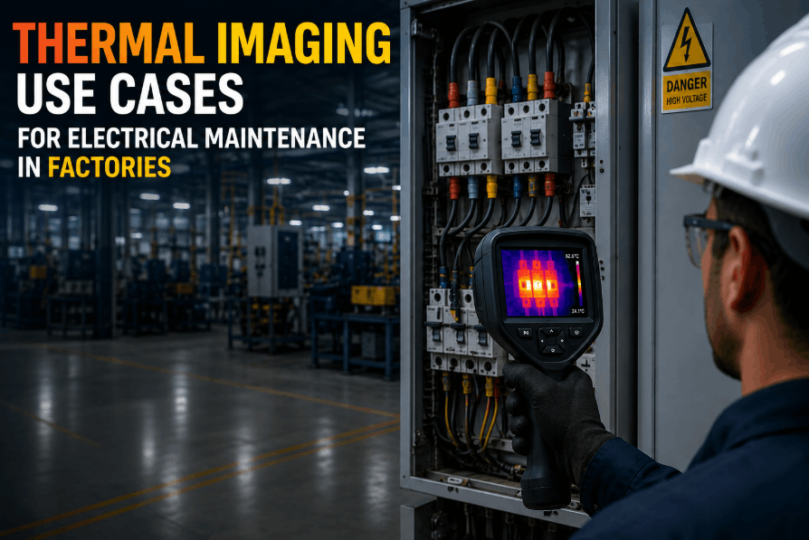
Perform infrared thermography survey of all panels, switchgear, and distribution equipment under minimum 40% of normal operating load — NFPA 70B 2023 requires this inspection at intervals not exceeding 12 months for all electrical equipment
Document thermal images and record temperature differentials — a delta-T above 10°C between similar components indicates a developing fault requiring follow-up; above 40°C requires immediate corrective action before next operation
Perform insulation resistance (IR) test on all feeder cables using 500V or 1000V megohmmeter — record readings and compare against baseline; declining trend over consecutive annual tests is more significant than any single reading
Conduct Polarization Index test on critical cable runs — measure IR at 1 minute and 10 minutes; PI ratio below 2.0 indicates moisture contamination or significant insulation degradation requiring investigation before continued operation
Perform harmonic analysis at main distribution panels — Total Harmonic Distortion above 5% causes excess heating in neutral conductors, transformers, and motors connected to that distribution system
Breaker Testing & System Documentation
Test circuit breaker trip function on all critical breakers using a calibrated breaker test set — verify breakers trip within manufacturer-specified time at 100%, 150%, and 300% of rated current to confirm protection curves are intact
Exercise all circuit breakers through at least one full open-close cycle — breakers that have not been operated develop mechanical stiffness and contact oxidation that prevents reliable operation when protection is needed most
Inspect and clean switchgear and motor control center (MCC) compartments — remove dust accumulation from bus compartments, which acts as a conductive path that lowers the effective insulation resistance between phases
Verify transformer cooling fins, fans, and oil levels where applicable — transformer overheating is a silent failure mode; check winding temperature indicators and compare against rated limits under operating load
Update single-line diagrams and panel schedules to reflect any changes made during the year — facilities that cannot produce an accurate one-line diagram have an automatic compliance deficiency under NFPA 70B 2023
Record all test results in the facility electrical maintenance log — NFPA 70B 2023 requires documentation of all maintenance activities; this record is what demonstrates due diligence in the event of an OSHA investigation
Every 5 Years
System Studies & Coordination Review
Licensed electrical engineer · Short-circuit & arc flash study · Full coordination analysis
Short-Circuit & Coordination Studies
Perform short-circuit study to calculate available fault current at all distribution levels — NFPA 70B 2023 requires these studies at intervals not exceeding 5 years; utility-side changes can increase fault current beyond equipment interrupting ratings
Conduct coordination study to verify protective device settings allow the closest upstream device to clear a fault before tripping a larger upstream breaker — miscoordination causes unnecessary widespread outages from localized faults
Verify all protective device ratings against current calculated fault levels — breakers and fuses rated below available fault current can fail catastrophically and explosively rather than interrupting the fault safely
Arc Flash Study & Label Update
Perform arc flash incident energy analysis at all electrical equipment locations — NFPA 70B aligns with NFPA 70E's requirement to review arc flash risk assessments at least every 5 years or whenever significant system changes occur
Update arc flash hazard labels on all panels, switchgear, and MCCs based on current study results — labels must reflect current incident energy levels and required PPE category; outdated labels expose workers to uncalculated risk
Review and update the facility Electrical Safety Program (ESP) to reflect current equipment configuration, personnel responsibilities, and PPE requirements — OSHA investigators request the ESP as first documentation in any electrical incident investigation
Thermal Imaging: What the Temperature Differential Tells You
Infrared thermography is now the most important diagnostic tool in electrical panel maintenance — and the only way to detect high-resistance connections before they cause a failure. A single temperature reading means little; it is the differential between similar components, and the trend across annual scans, that reveals where your system is under stress.
Delta-T below 10°C
Monitor
Within normal variation range. Document as baseline and continue annual scanning. No immediate action required but note in trend log for comparison next year.
Delta-T 10°C – 25°C
Investigate
Elevated differential indicating developing fault. Schedule follow-up inspection and torque verification at next planned maintenance window. Increase inspection frequency to quarterly.
Delta-T 25°C – 40°C
Priority Action
Significant resistance fault confirmed. Schedule corrective action within 30 days. Do not wait for the next planned maintenance cycle. Increase monitoring to monthly until repaired.
Delta-T above 40°C
Immediate Action
Critical fault with imminent failure risk. Take the circuit out of service at the earliest possible opportunity and repair before next energization. Document and escalate to facility management immediately.
Insulation Resistance Test — Reading Interpretation
Above 100 MΩ
Excellent — Annual testing, record for trend
10 – 100 MΩ
Acceptable — Increase to quarterly testing
1 – 10 MΩ
Investigate — Conduct PI test, check for moisture
Below 1 MΩ
Do Not Energize — Schedule repair immediately
Always correct IR readings to 20°C for consistent comparison across tests — insulation resistance approximately doubles for every 10°C drop in temperature, making uncorrected readings from different seasons incomparable. The trend across three or more consecutive annual tests is far more informative than any single reading.
Maintenance Interval Quick Reference
| Maintenance Task |
Monthly |
Quarterly |
Annual |
Every 5 Years |
| Visual panel inspection & enclosure check |
Required |
— |
— |
— |
| Arc flash label verification |
Visual check |
— |
Full audit |
Update from study |
| Phase voltage & load current measurement |
— |
Measure & record |
Full power quality |
— |
| Connection torque verification |
— |
All terminations |
— |
— |
| Grounding continuity & resistance test |
Visual check |
Resistance test |
Full ground audit |
— |
| GFCI & overload relay function test |
— |
Test all devices |
— |
— |
| Infrared thermography survey |
— |
— |
Mandatory (NFPA 70B) |
— |
| Insulation resistance (IR) & PI testing |
— |
— |
Full IR & PI test |
— |
| Circuit breaker trip function testing |
— |
— |
Calibrated test set |
— |
| Harmonic distortion analysis |
— |
— |
THD measurement |
— |
| Single-line diagram update |
— |
— |
Review & update |
— |
| Short-circuit & coordination study |
— |
— |
— |
Licensed engineer |
| Arc flash incident energy analysis |
— |
— |
— |
Full study & label update |
Build a Compliance-Ready Audit Trail — Automatically
OxMaint captures every IR test reading, thermal imaging result, breaker test record, and grounding measurement in a searchable digital history. When OSHA asks for your electrical maintenance documentation, it is one report — not a filing cabinet.
Frequently Asked Questions
Is infrared thermography now legally required for electrical panels?
The 2023 NFPA 70B standard has made infrared thermography of all electrical equipment mandatory at intervals not exceeding 12 months — a significant shift from the previous version, which only recommended it. While NFPA 70B is not directly written into federal law, OSHA can cite non-compliance under the General Duty Clause if an incident occurs and the facility cannot demonstrate it followed recognized industry standards. In practice, this means most insurers and risk managers now treat annual IR scanning as non-negotiable. A digital PM platform like OxMaint ensures your thermography schedule never lapses and your documentation is compliance-ready on demand.
How often should circuit breakers be tested and what does the test involve?
Circuit breakers should be tested annually using a calibrated breaker test set that injects current at 100%, 150%, and 300% of the breaker's rated amperage and measures the actual trip time against the manufacturer's published time-current curve. Breakers that are never operated develop mechanical stiffness and contact oxidation that can prevent them from tripping under a real fault condition — a failure mode that produces no visible warning. In addition to trip testing, all breakers should be exercised through at least one full open-close cycle annually. Tracking test results and trip time trends in a CMMS lets you identify breakers whose trip times are drifting before they fail to protect under load.
What is an arc flash study and when does it need to be updated?
An arc flash study is an engineering calculation that determines the incident energy a worker could be exposed to at each piece of electrical equipment during a fault, which defines the required PPE category and approach boundaries. NFPA 70B and NFPA 70E together require the study to be reviewed at least every 5 years, or whenever significant changes are made to the electrical system — including utility upgrades, equipment additions, or changes to protective device settings. Without a current study, your arc flash labels may specify insufficient PPE, exposing workers to uncalculated risk. OxMaint tracks the due date of your arc flash study and flags it for renewal alongside your regular PM schedule.
What grounding resistance value indicates a problem that needs immediate attention?
Grounding resistance should measure below 1 ohm for most industrial and commercial electrical systems — this threshold ensures the ground path presents low enough impedance to allow fault current to flow at a level that will trip protective devices reliably. Readings between 1 and 5 ohms indicate a degraded connection that should be repaired at the next planned maintenance window. Readings above 5 ohms represent a seriously compromised ground system that increases both shock hazard and arc flash severity, requiring prompt repair rather than deferred action. Always retest after any repair using a calibrated fall-of-potential or clamp-type ground resistance tester to verify the correction was effective and document the before-and-after readings in your maintenance management system.
What documentation does OSHA expect to see after an electrical incident?
OSHA investigators typically request the facility's Electrical Safety Program (ESP), the most recent arc flash study and updated hazard labels, training records for qualified persons who performed work on the affected equipment, and all maintenance records for the equipment involved — including when it was last inspected, tested, and by whom. Facilities that rely on paper-based maintenance logs frequently cannot produce complete records quickly, which compounds both the compliance exposure and the investigation outcome. A digital audit trail maintained in OxMaint makes every inspection record, technician signature, and test result retrievable in minutes — the exact documentation posture that demonstrates due diligence under the NFPA 70B standard.