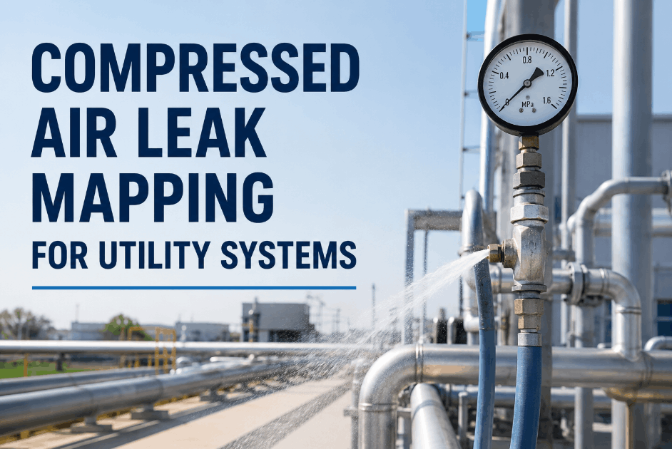
Pump failures rarely arrive as a single dramatic event. They build up over weeks — a bearing running a few degrees hotter, a seal weeping a drop more per minute, a vibration reading climbing a millimetre per second per shift — until the day the line stops and a six-figure repair bill shows up. Manufacturing plants that run a structured pump maintenance checklist catch every one of those early signals; plants that rely on memory and informal walk-arounds catch them only after the failure. The difference shows up in MTBF, energy bills, and the size of the spare parts inventory needed to keep the place running. Use this six-system checklist to inspect every centrifugal pump on your floor the way reliability engineers do — backed by ISO 10816-7 vibration thresholds and BEP performance benchmarks — and turn every round into structured digital evidence with OxMaint's industrial pump maintenance platform.
Industrial · Centrifugal Pumps · Reliability
Pump Maintenance Checklist for Industrial and Manufacturing Plants
Six systems. Thirty inspection points. ISO 10816-7 vibration zones, vibration-signature diagnostics, and a frequency matrix tied to daily, weekly, monthly, quarterly, and annual cadences — built for reliability engineers, mechanical technicians, and rotating-equipment leads.
$10K–$250K
Industry-cited cost per hour of unplanned downtime on rotating equipment
67%
Of pump failures trace back to lubrication or bearing defects per Midwest plant studies
30–40%
Of bearing life lost when vibration intensity doubles per ANSI/HI 9.6.4
ISO 10816-7
International vibration severity standard for industrial pumps above 1 kW
ISO 10816-7 Severity Zones
Read Every Vibration Reading Against These Four Zones
A vibration number in millimetres per second only tells you something when you compare it against a recognised severity zone. ISO 10816-7 defines four zones — Good, Acceptable, Unsatisfactory, and Damage — that turn raw readings into clear maintenance actions. Use these as the threshold logic in every inspection round.
A
Good
≤ 1.8 mm/s RMS
Newly commissioned or precision-balanced pumps. Continue routine monitoring.
B
Acceptable
1.8 – 3.5 mm/s RMS
Long-term unrestricted operation permitted. Trend monthly to catch drift early.
C
Unsatisfactory
3.5 – 7.1 mm/s RMS
Plan corrective work within current operating period. Investigate alignment, balance, lubrication.
D
Damage
> 7.1 mm/s RMS
Take out of service as soon as practical. Continued operation risks bearing, seal, and shaft damage.
Values shown are typical thresholds for medium horizontal pumps on rigid foundations. Always verify against the specific category and foundation type for your unit.
01
Bearings & Lubrication
Roughly two-thirds of pump failures trace to lubrication or bearing defects. Bearing condition is the most reliable leading indicator of impending pump failure and the cheapest item to monitor proactively.
Bearing temperature trended against baseline
A bearing running 15 degrees hotter than its baseline is failing — even if still within absolute spec. Trend the value, not just the snapshot.
Lubricant level, color, and clarity
Oil should be clear with no frothing or cloudiness. Cloudy oil indicates water ingress; frothing indicates over-fill or aeration. Both call for immediate change.
Vibration at each bearing per ISO 10816-7
Measure horizontal, vertical, and axial RMS at every bearing housing. Compare against the zone chart and trend any reading that crosses zone B into zone C.
Greasing interval on schedule with correct quantity
Follow OEM grease intervals exactly. Over-greasing forces grease past seals into the lubricant pathway and is just as damaging as under-greasing.
Bearing housing integrity — no cracks, oil seal condition
Inspect the housing for hairline cracks, corrosion, and oil seal weeping. A failed shaft seal contaminates the lubricant within hours under load.
02
Mechanical Seals & Packing
Seal failure is consistently cited as the single most common pump failure mode — and the root cause is almost always something else: shaft deflection, vibration, misalignment, or a starved flush plan. Inspect both the seal and the conditions feeding it.
Mechanical seal — no visible leakage at the gland
Mechanical seals should run dry on the outside. Any visible drip is a finding — log the rate and investigate before it becomes a spray.
Packing leakage rate within normal range
A packed pump should leak 40 to 60 drops per minute for cooling and lubrication. Zero leakage means the packing is over-tightened — bearings and shaft pay the cost.
Seal flush plan operational and within design
Verify Plan 11, 13, 21, 32, or whichever API plan applies. Flow, pressure, and temperature at the seal must match the plan that protects it.
O-rings and gaskets at seal chamber
Inspect seal chamber gaskets and O-rings during every overhaul. Replace as a matter of course — these parts cost pennies but cause hours of downtime when they fail.
Barrier or buffer fluid pressure within spec
Dual seal systems rely on the right barrier pressure to keep process fluid out. Verify the reservoir level and pressure on every round.
03
Shaft Alignment & Coupling
Misalignment of even a few thousandths of an inch forces shafts to flex once per revolution — cyclic fatigue stress that destroys bearings, leaks seals, and lifts power consumption. Laser alignment is the industry standard; dial indicators are acceptable when calibrated.
Coupling alignment within OEM tolerance
Verify both angular and parallel offset against OEM tolerance — typically under 0.002 inches per inch of coupling face. Laser alignment gives quantifiable results.
Coupling element condition — no wear or cracking
Inspect the coupling sleeve, grid, or jaw insert for chunks missing, cracks, or rubber hardening. A failing element accelerates misalignment effects.
Shaft runout measured and within spec
Shaft runout greater than 0.002 inches signals a bent shaft, worn coupling hub fit, or bearing damage. Replace or rebuild as appropriate.
Hot-versus-cold alignment offset accounted for
Pumps handling hot fluid grow thermally — cold alignment must offset the expected growth. Use OEM thermal growth data or vendor calculation.
Coupling guard secure and compliant
Guards must cover all rotating parts per 29 CFR 1910.219 and not have any access path that defeats the protection. A removed guard during operation is a stop-work finding.
Capture every reading, photo, and finding on a phone — and let OxMaint trend bearing temperatures, vibration values, and seal leak rates across every pump in the plant. No more clipboards, no more lost data, no more failures that nobody saw coming.
04
Performance & Vibration Monitoring
A pump operating away from its Best Efficiency Point carries higher hydrodynamic load and shorter component life. Performance monitoring is what tells you the pump is running where it was designed to run — not just that it is running.
Suction and discharge pressures within design curve
Compare current head against the OEM performance curve at the measured flow. A drop in head at the same flow signals internal wear or recirculation.
Flow rate within ±5 percent of expected
Flow drift suggests wear ring damage, impeller erosion, or a partially closed valve downstream. Verify before assuming the pump is the cause.
Motor amp draw within nameplate FLA
Rising amp draw means rising load — usually internal friction, partial blockage, or rotor drag. Investigate the source rather than tolerating the trend.
Vibration RMS within ISO 10816-7 zone B
Routine operating equipment should sit in zone A or low zone B. A reading climbing into zone C requires investigation; zone D requires shutdown.
Operating point within ±10 percent of BEP
Deadheading or starving the pump puts hydrodynamic load on the impeller and seal. Either fix the system or specify a pump correctly sized for the duty.
05
Impeller, Casing & Wear Rings
Internal wear shows up first as a gradual drop in head and flow rate, long before any external symptom. Wear rings, impellers, and casings reveal whether the pump is degrading internally — and whether the next overhaul should be scheduled or deferred.
Casing exterior — no cracks, corrosion, or pitting
Walk the casing visually each round. Hairline cracks, weeping flanges, and visible pitting all signal internal pressure stress or chemical attack.
Impeller condition — balance, erosion, vane wear
During overhaul, inspect impeller vanes for erosion patterns. Asymmetric wear indicates flow recirculation or operation off BEP — fix the root cause.
Wear ring clearance within OEM specification
Typical new clearance runs 0.012 to 0.020 inches. When measured clearance reaches twice OEM, internal recirculation drops capacity and head — replace the rings.
Casing bolts torqued to spec, gasket joint sealed
Torque-check casing fasteners during every PM. A leaking case bolt is a gasket replacement waiting to escalate to a full disassembly.
Drain plugs, vent plugs, and casing fittings intact
Inspect each fitting for corrosion, cross-threading, and seating. Replace any that have been disturbed during sampling or draining.
06
Suction, Discharge & Foundation
A perfectly maintained pump still fails if the system around it is fighting it. Pipe strain, plugged strainers, and a cracked grout line all transmit forces back into the pump that no internal maintenance can compensate for.
Suction strainer clean, differential pressure within spec
A loaded strainer starves the pump and forces cavitation. Trend the strainer differential pressure and clean before it crosses the alarm threshold.
Pipe supports and hangers in place, no flange strain
Inspect that piping is supported by its own hangers — never by the pump flanges. Pipe strain is one of the most under-recognised causes of pump failure.
Suction-side air leaks ruled out
Air leaks on the suction side cause erratic flow, cavitation, and noise. Soap-test suction joints and verify gasket condition during every PM.
Discharge valves operate fully open and closed
A discharge valve stuck partially closed is the same as a permanent throttling condition. Verify full stroke quarterly and during every shutdown.
Foundation, baseplate, and grout integrity
Cracked grout under the baseplate transmits vibration and breaks alignment. Check hold-down bolt torque and the baseplate-to-foundation joint quarterly.
Vibration Signature Decoder
What Your Vibration Frequencies Are Actually Telling You
Total vibration RMS tells you something is wrong. The frequency spectrum tells you what. These four signature patterns cover the vast majority of pump faults found by routine vibration analysis — translate the frequency, then translate the action.
Pattern 01
Peak at 1× Running Speed
Diagnosis: Rotor Imbalance
Likely from missing balance weight, debris on the impeller, or accumulated solids. Action: clean the impeller and re-balance to the appropriate ISO 1940 grade.
Pattern 02
Peak at 2× Running Speed (Often Axial)
Diagnosis: Coupling Misalignment
Classic 2× signature, frequently with strong axial component. Action: laser-align the coupling cold, verify hot offset, and inspect the coupling element.
Pattern 03
High-Frequency, Non-Harmonic Spikes
Diagnosis: Bearing Defect
Energy at bearing defect frequencies, broadband elevation in the high spectrum. Action: replace the bearing, verify lubrication, and root-cause the failure mode.
Pattern 04
Random / Broadband Noise Floor
Diagnosis: Cavitation
Random energy across the spectrum, often with audible gravel-in-pump noise. Action: verify NPSHa, clear the strainer, and return the pump to its BEP operating range.
Frequency Matrix
What to Inspect — and How Often
Every pump system has its own rhythm of attention. Use this matrix to assign inspections by role and frequency rather than relying on individual technician memory or shift handovers. Scroll horizontally on mobile to see all five cadences.
| System |
Daily |
Weekly |
Monthly |
Quarterly |
Annual |
| Bearings & Lubrication |
Visual and noise check |
Lubricant level and temperature |
Vibration spectrum reading |
Oil change or sample for analysis |
Bearing replacement by hours or condition |
| Mechanical Seals & Packing |
Drip count at seal |
Packing adjustment if needed |
Seal flush plan verification |
Detailed seal inspection |
Seal or packing replacement |
| Alignment & Coupling |
Visual at coupling guard |
Guard fit and bolt tightness |
Alignment verification with dial or laser |
Re-align if offset exceeds tolerance |
Coupling element inspection or replacement |
| Performance & Vibration |
Pressure and flow log |
Motor amp draw log |
Compare current point to BEP |
Performance test at known conditions |
Full performance curve verification |
| Impeller, Casing & Wear Rings |
External casing visual |
Casing bolt torque check |
Vibration trend review |
Internal borescope where accessible |
Disassemble and inspect during overhaul |
| Piping, Foundation & Mounting |
Visual for leaks and drips |
Strainer differential pressure |
Pipe support and hanger condition |
Pipe alignment and flange check |
Foundation grout and baseplate audit |
Reliability KPIs
Five Numbers That Prove Your Pump Program Is Working
A pump maintenance program without measurable outcomes drifts back into reactive mode within a quarter. These five KPIs, reviewed monthly, keep the program honest and tied to plant outcomes.
MTBF per Pump
Mean operating hours between unplanned stops
Target: rising trend over 12 months
Vibration RMS Trend
Monthly average against ISO 10816-7 zones
Target: stay in zone A or low zone B
BEP Deviation
Operating point distance from Best Efficiency Point
Target: within ±10 percent of BEP
Specific Energy Use
kWh per cubic metre pumped or per ton handled
Target: declining month-on-month
Seal MTBR
Mean time between seal repairs across the fleet
Target: rising trend year-on-year
FAQs
Frequently Asked Questions
How often should industrial pumps be inspected?
Run daily sensory checks during operation, weekly hands-on rounds, monthly comprehensive PMs covering vibration and lubrication, quarterly system-level reviews, and annual overhauls during planned shutdowns.
Book a demo to see how OxMaint schedules each cadence by pump.
What is the most common cause of pump failure?
Seal failure is the most cited single failure mode, but the root cause is almost always lubrication issues, misalignment, or vibration that stresses the seal. About 67 percent of pump failures trace back to lubrication or bearing defects per Midwest plant studies.
Get started with OxMaint to trend root-cause data fleet-wide.
What vibration level is acceptable for industrial pumps?
ISO 10816-7 sets four zones: zone A (good) under 1.8 mm/s RMS, zone B (acceptable) up to 3.5 mm/s, zone C (unsatisfactory) up to 7.1 mm/s, and zone D (damage) above 7.1 mm/s. Specific thresholds depend on pump category and foundation.
Book a demo to see how OxMaint logs readings against zones.
What is BEP and why does it matter for pump maintenance?
Best Efficiency Point is the flow at which a pump produces minimum hydrodynamic unbalanced load. Operating far from BEP shortens bearing and seal life and raises energy consumption — even when the pump appears to run normally.
Start free and trend BEP deviation across every pump.
Can a CMMS reduce pump failures and maintenance costs?
Yes. A CMMS like OxMaint converts paper rounds into mobile-completed digital workflows, auto-generates work orders from findings, trends bearing temperatures and vibration values across every pump, and stores photo evidence and data history for reliability decisions.
Book a demo to see it in action.
Run Every Pump Round Through OxMaint
Mobile checklists, vibration logs, photo evidence, automatic work orders, and trend data — built for manufacturing plants that refuse to let small bearing or seal issues become production-line shutdowns.