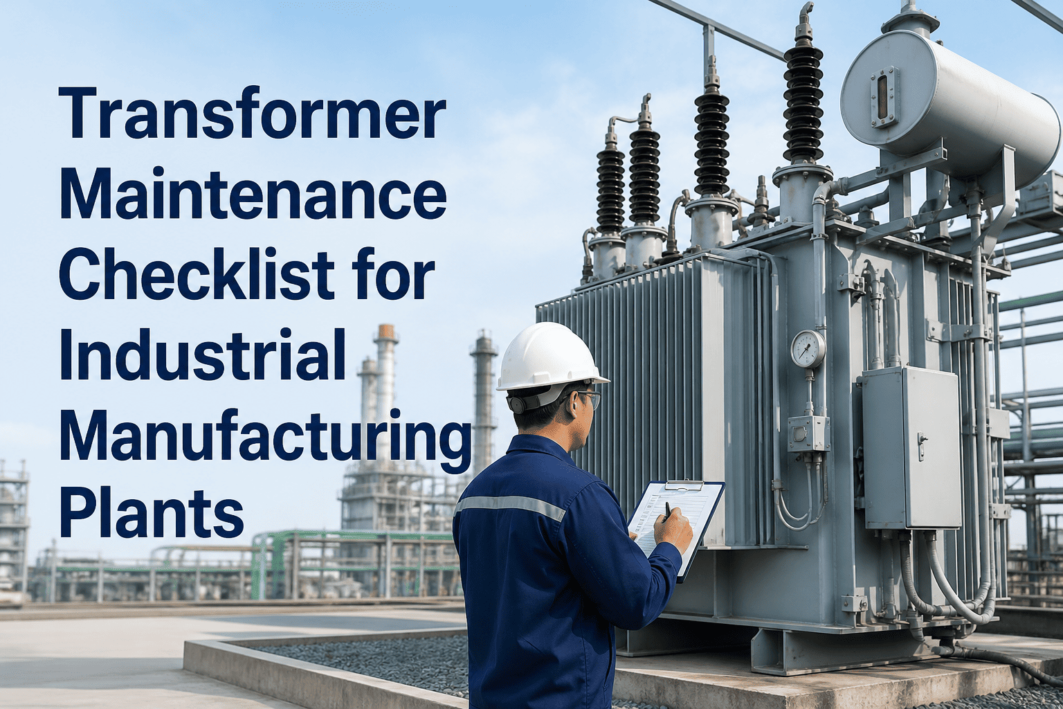
A transformer failure doesn't just disrupt your production schedule — it can trigger cascading electrical faults, catastrophic fires, and plant-wide shutdowns that extend for weeks while replacement units are procured and commissioned. Industrial transformers — from 100 kVA distribution units to multi-MVA substation transformers — are the backbone of your facility's electrical infrastructure, and neglecting oil quality, insulation resistance, or cooling system performance creates risks that no maintenance team can afford. This inspection checklist provides electrical engineers and high-voltage technicians with a structured approach to transformer preventive maintenance, covering dissolved gas analysis, insulation testing, tap changer servicing, and thermal surveys. Every checkpoint in this guide is designed to detect degradation before it becomes a failure, giving you the lead time to schedule outages on your terms instead of emergency response timelines. OxMaint's electrical asset management module helps power distribution teams track transformer test results, oil analysis trends, and regulatory compliance in one centralized platform.
Zone 1 — Insulating Oil Analysis
Zone 2 — Winding & Insulation Tests
Zone 3 — Cooling System Checks
Zone 4 — Tap Changer Inspection
Zone 5 — Bushing & Terminal Review
Zone 6 — Protection & Control Validation
Transformer Failure Root Causes
Oil contamination & degradation
38%
Overloading & overheating
12%
Bushing failure & tracking
8%
Zone 01
Insulating Oil Analysis & Condition Monitoring
Transformer oil serves dual functions — electrical insulation and heat transfer. Oil degradation accelerates winding insulation aging and increases internal arcing risk. Dissolved gas analysis (DGA) is the single most predictive diagnostic tool for detecting incipient faults months before they manifest as measurable electrical failures.
Perform dissolved gas analysis (DGA) to measure H₂, CH₄, C₂H₄, C₂H₆, C₂H₂, CO, and CO₂ concentrations — interpret results per IEEE C57.104 Duval Triangle method
Test: Annual or on-alarm · Owner: Electrical Engineer · Standard: IEEE C57.104
Test oil dielectric breakdown voltage per ASTM D1816 — minimum acceptable value is 30 kV for distribution transformers, 40 kV for substation units
Test: Annual · Owner: HV Technician · Standard: ASTM D1816
Measure oil moisture content using Karl Fischer titration — target < 15 ppm for transformers rated above 69 kV, < 25 ppm for lower voltage units
Test: Annual · Owner: Laboratory Technician · Standard: ASTM D1533
Verify oil acidity (neutralization number) remains below 0.15 mg KOH/g — rising acidity indicates oxidation and accelerates insulation paper degradation
Test: Annual · Owner: Oil Lab Analyst · Standard: ASTM D974
Inspect oil level in conservator tank or expansion chamber — low level may indicate leaks or thermal expansion issues requiring investigation
Inspection: Monthly · Owner: Electrical Technician · Safety: De-energized inspection preferred
Check oil color and clarity through sight glass — darkening indicates oxidation; cloudiness signals moisture contamination or particle suspension
Inspection: Monthly · Owner: Electrical Technician · Action: Sample and test if abnormal
Verify breather silica gel desiccant condition — replace when color indicator changes from blue to pink showing moisture saturation
Inspection: Monthly · Owner: Electrical Technician · Replacement: As needed
Zone 02
Winding Insulation & Electrical Testing
Transformer winding insulation degrades over time due to thermal stress, moisture ingress, and electrical stress from transients. Insulation resistance and power factor testing provide early warning of deterioration that could lead to turn-to-turn shorts or ground faults.
Measure insulation resistance using 5 kV megohmmeter for all winding-to-ground and winding-to-winding combinations — record temperature-corrected values and compare to baseline
Test: Annual or after major maintenance · Owner: HV Test Technician · Standard: IEEE 62-1995
Calculate polarization index (PI) as 10-minute resistance divided by 1-minute resistance — PI values below 2.0 indicate moisture or contamination issues
Test: Annual · Owner: Electrical Engineer · Acceptance: PI ≥ 2.0
Perform power factor or dissipation factor testing on bushings and windings — rising power factor trends indicate insulation deterioration requiring corrective action
Test: Biennial or on-alarm · Owner: Electrical Test Specialist · Standard: IEEE C57.12.90
Measure DC winding resistance on all phases and tap positions — compare to factory test report values; deviations exceeding 2% indicate connection issues or shorted turns
Test: Annual · Owner: HV Technician · Standard: IEEE C57.12.90
Verify turns ratio across all tap positions using a transformer turns ratio (TTR) tester — ratio deviation beyond ±0.5% of nameplate requires investigation
Test: Annual · Owner: Electrical Engineer · Equipment: TTR tester
Conduct polarity and phase relationship verification to confirm correct primary-secondary winding connections before re-energizing after maintenance
Test: Post-maintenance commissioning · Owner: Electrical Engineer · Safety: Critical
Track all transformer test results, oil analysis trends, and regulatory compliance documentation in one system — OxMaint's electrical asset module centralizes your high-voltage PM records and flags overdue inspections automatically.
Zone 03
Cooling System Inspection & Maintenance
Transformer cooling systems — oil circulation pumps, radiator fans, and heat exchangers — are critical for maintaining winding temperatures within design limits. Cooling system failures cause rapid temperature rise, accelerating insulation aging and potentially triggering thermal runaway.
Inspect radiator fins and cooling panels for blockage from dirt, leaves, or debris — clean with compressed air or water wash to restore heat transfer efficiency
Inspection: Quarterly · Owner: Electrical Technician · Cleaning: As required
Check radiator valve positions and verify all cooling paths are open — closed valves reduce cooling capacity and cause localized overheating
Inspection: Quarterly · Owner: Electrical Technician · Action: Correct valve position
Inspect radiator mounting bolts and gaskets for oil seepage — leaking gaskets allow moisture ingress and reduce oil volume requiring immediate repair
Inspection: Quarterly · Owner: Maintenance Technician · Repair: Seal replacement
Test automatic cooling fan operation at temperature setpoints — verify fans start and stop correctly based on winding temperature indicator (WTI) or oil temperature indicator (OTI)
Test: Quarterly · Owner: Electrical Technician · Setpoint: Per manufacturer spec
Measure cooling fan motor current and compare to nameplate rating — overcurrent indicates bearing wear or blade damage requiring motor maintenance
Test: Quarterly · Owner: Electrical Technician · Tool: Clamp meter
Verify oil circulation pump operation (if forced-oil cooling) — check pump pressure differential, vibration, and bearing temperature during full-load conditions
Test: Quarterly · Owner: Mechanical Technician · Coordination: With electrical team
Record top oil temperature and winding temperature under normal load — compare to historical baseline; temperature rise above trend indicates cooling degradation or overloading
Monitoring: Weekly · Owner: Operations Technician · Alert: Temp rise > 10°C
Perform infrared thermal scan of transformer tank, bushings, and connections during peak load — hot spots indicate internal faults, loose connections, or cooling issues
Scan: Annual or on-alarm · Owner: Thermography Specialist · Standard: NETA ATS
Zone 04
Tap Changer Inspection & Servicing
On-load tap changers (OLTC) and off-circuit tap changers are high-wear mechanical components that adjust transformer voltage ratio. Contact erosion, drive mechanism failure, and oil contamination in OLTC compartments are leading causes of transformer outages in regulated voltage systems.
Count tap changer operations since last service — most manufacturers recommend full inspection every 50,000–100,000 operations or 5 years, whichever occurs first
Tracking: Continuous via operation counter · Owner: Electrical Engineer · Interval: Per OEM
Inspect OLTC oil separately from main tank oil — DGA on tap changer oil detects arcing and contact wear before main tank contamination occurs
Test: Annual or per operation count · Owner: Oil Lab Analyst · Standard: IEC 60567
Verify tap changer motor and drive mechanism operation — test both manual and automatic modes; listen for abnormal noise during tap change sequence
Test: Quarterly · Owner: Electrical Technician · Safety: Follow LOTO procedures
Confirm tap position indicator matches actual contact position by measuring output voltage at each tap — misalignment indicates mechanical slippage or indicator failure
Test: Annual · Owner: HV Technician · Equipment: True RMS voltmeter
Check tap changer control circuit interlocks and limit switches — verify cannot operate while transformer is carrying load (for off-circuit type)
Test: Annual · Owner: Control Technician · Safety: Critical interlock
Zone 05
Bushing & Terminal Inspection
Bushings provide insulated high-voltage connections through the transformer tank. Bushing failures cause catastrophic tank rupture and fire. Power factor testing, visual inspection, and thermal imaging detect degradation before flashover occurs.
Perform capacitance and power factor testing on all HV and LV bushings — power factor increase exceeding 1% from baseline indicates moisture ingress or internal degradation
Test: Biennial or on-alarm · Owner: HV Test Specialist · Standard: IEEE C57.19.01
Inspect bushing oil level (for oil-filled bushings) through sight glass — low oil indicates leak requiring immediate repair before internal flashover risk develops
Inspection: Monthly · Owner: Electrical Technician · Urgency: High priority
Inspect bushing porcelain for cracks, chips, or carbon tracking — any visible damage requires immediate replacement as flashover risk is imminent
Inspection: Monthly · Owner: Electrical Technician · Safety: Binoculars for HV bushings
Check terminal connections for corrosion, looseness, or overheating — torque all bolted connections to manufacturer specification using calibrated torque wrench
Inspection: Annual · Owner: HV Technician · Tools: Torque wrench, contact cleaner
Perform infrared scan of all bushing connections under load — temperature differentials exceeding 15°C between phases indicate high resistance connections requiring maintenance
Scan: Annual · Owner: Thermography Specialist · Baseline: Compare phase-to-phase
Zone 06
Protection & Control System Validation
Transformer protective relays — Buchholz gas relay, pressure relief devices, differential protection, and thermal overload — must operate correctly during fault conditions. Annual functional testing ensures protection coordination and prevents false trips or failure-to-trip scenarios.
Test Buchholz relay (gas accumulation relay) operation by simulating gas accumulation — verify alarm and trip contacts operate at correct gas volumes per manufacturer settings
Test: Annual · Owner: Protection Technician · Standard: IEC 60044-5
Verify sudden pressure relay operation using test equipment — confirm relay trips circuit breaker within design time during simulated internal fault pressure surge
Test: Annual · Owner: Relay Technician · Equipment: Pressure test kit
Conduct differential relay testing by injecting secondary currents — verify relay characteristic curve matches settings and trips for internal faults while remaining stable during external faults and inrush
Test: Annual · Owner: Protection Engineer · Equipment: Relay test set
Calibrate winding temperature indicator (WTI) and oil temperature indicator (OTI) using reference thermometer — verify alarm and trip setpoints match protection scheme
Calibration: Annual · Owner: Instrumentation Technician · Standard: ±2°C accuracy
Test pressure relief device operation — verify venting pressure matches nameplate rating and device reseats after operation (non-destructive test or visual inspection only)
Inspection: Annual visual / 5-year functional test · Owner: Electrical Engineer · Safety: Critical
Verify control power supply voltage and battery backup (if UPS-backed) — test automatic switchover during AC power loss to ensure protection remains active
Test: Quarterly · Owner: Control Technician · Backup: Battery load test annual
Update transformer asset record in CMMS with all test results, inspection findings, and maintenance actions — complete documentation is required for insurance claims and regulatory audits
Documentation: After every inspection · Owner: Maintenance Planner · System: CMMS
Performance Tracking
Transformer Maintenance KPIs
| Metric |
Measurement Method |
Target Value |
Review Frequency |
| Oil Dielectric Strength |
ASTM D1816 breakdown voltage test |
> 30 kV (distribution) / > 40 kV (substation) |
Annual |
| Oil Moisture Content |
Karl Fischer titration (ppm) |
< 15 ppm (> 69 kV) / < 25 ppm (lower voltage) |
Annual |
| Insulation Resistance (PI) |
Polarization index (10 min / 1 min ratio) |
> 2.0 |
Annual |
| DGA Gas Levels |
Per IEEE C57.104 limits |
All gases within normal range |
Annual or on-alarm |
| Cooling System Availability |
Fan/pump operational hours / total hours |
> 98% |
Monthly |
| PM Inspection Completion |
Completed inspections / scheduled inspections |
100% |
Monthly |
Expert Insights
What Electrical Engineers Know About Transformer Reliability
01
Dissolved gas analysis caught an incipient winding fault six months before thermal failure would have occurred. The repair cost $40K during a planned outage. The emergency replacement quote was $380K with 12-week lead time. DGA pays for itself the first time it saves you from catastrophic failure.
Senior Electrical Engineer, Petrochemical Facility
02
We track every transformer test result in OxMaint and set automated alerts when oil breakdown voltage drops below 35 kV or moisture exceeds 20 ppm. Before CMMS, test reports lived in file cabinets and we only noticed trends after failures. Now we intervene early.
Electrical Maintenance Manager, Manufacturing Plant
03
Tap changer maintenance is the most neglected transformer PM task. We now service our OLTCs every 50,000 operations religiously after a tap changer fire took down our main substation for three weeks. The inspection interval exists for a reason — follow it.
Chief Electrical Officer, Automotive Assembly Plant
Common Questions
Transformer Maintenance FAQs
How often should transformer oil be tested?
Annual oil testing is the minimum for critical transformers. This includes dielectric breakdown, moisture content, acidity, and dissolved gas analysis. High-criticality units or those showing degradation trends may require quarterly or semi-annual testing.
What do dissolved gas analysis results indicate?
DGA detects fault gases produced by overheating, arcing, or corona discharge inside the transformer. Specific gas combinations indicate fault types — acetylene suggests arcing, ethylene indicates overheating above 700°C, and hydrogen points to corona or low-energy partial discharge.
When should transformer insulation resistance be measured?
Annual insulation resistance testing is standard practice. Additional testing is required after major maintenance, extended storage, moisture exposure, or whenever there is suspicion of insulation degradation. Always test before re-energizing after long shutdowns.
How can I track transformer maintenance in a CMMS?
Create asset records for each transformer with nameplate data, test history, and oil analysis trends. Schedule recurring PM tasks for inspections, testing, and oil sampling. OxMaint's electrical module stores DGA results, insulation tests, and thermal scans in one location with automated compliance tracking.
What is the leading cause of transformer failures?
Oil contamination and degradation account for approximately 40% of transformer failures. Moisture ingress, oxidation, and dissolved combustible gases reduce dielectric strength and accelerate insulation aging, making oil quality monitoring the highest-ROI preventive maintenance investment.
Manage Your Electrical Asset Maintenance the Way Reliability Demands
OxMaint's CMMS gives electrical teams centralized tracking for transformer test results, oil analysis trends, regulatory compliance deadlines, and PM scheduling — everything you need to prevent failures instead of reacting to them.