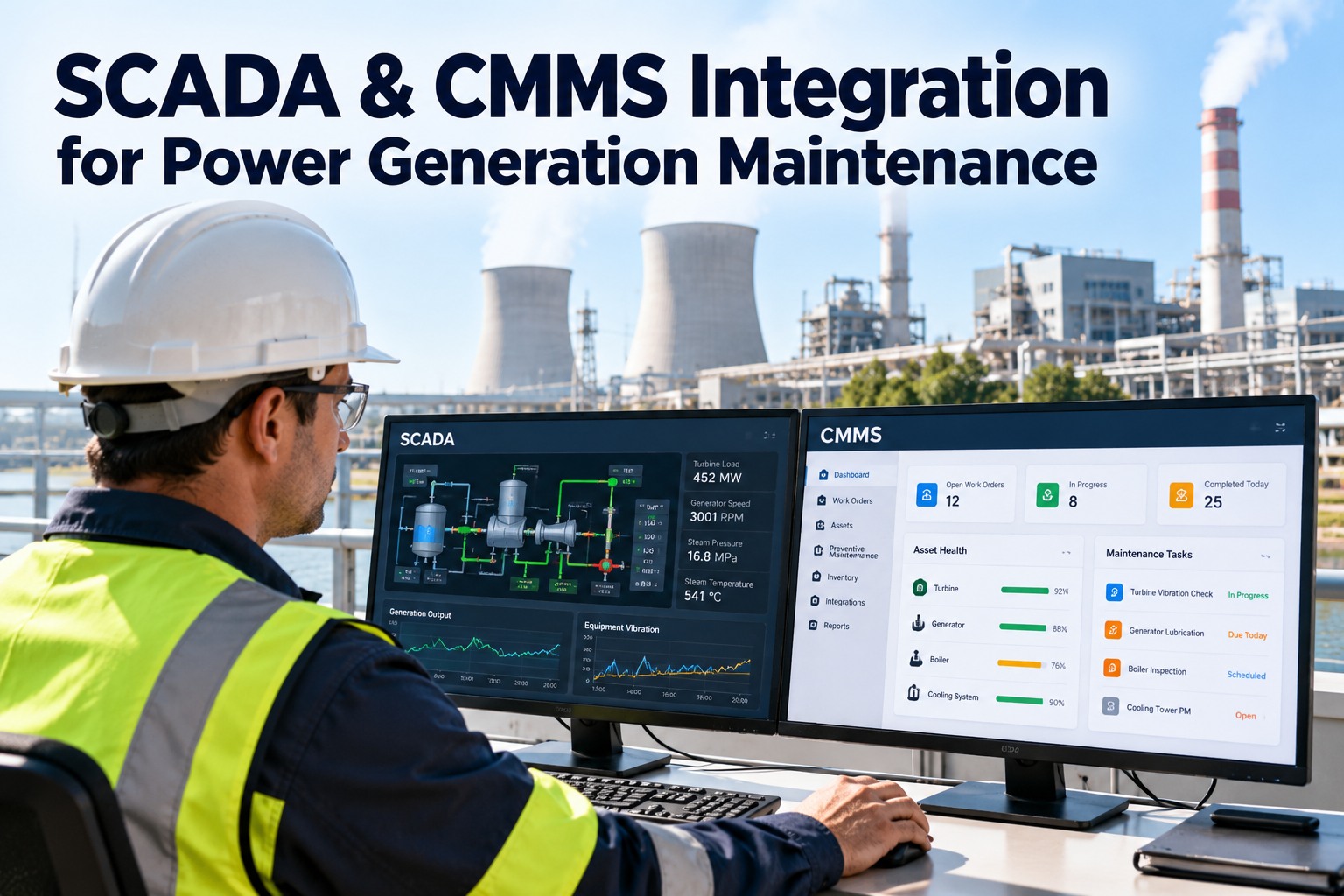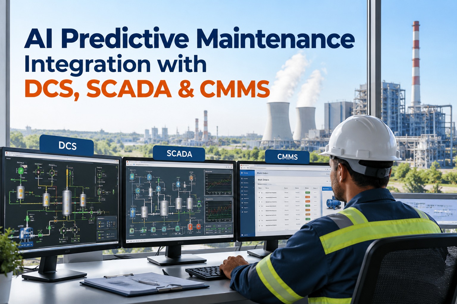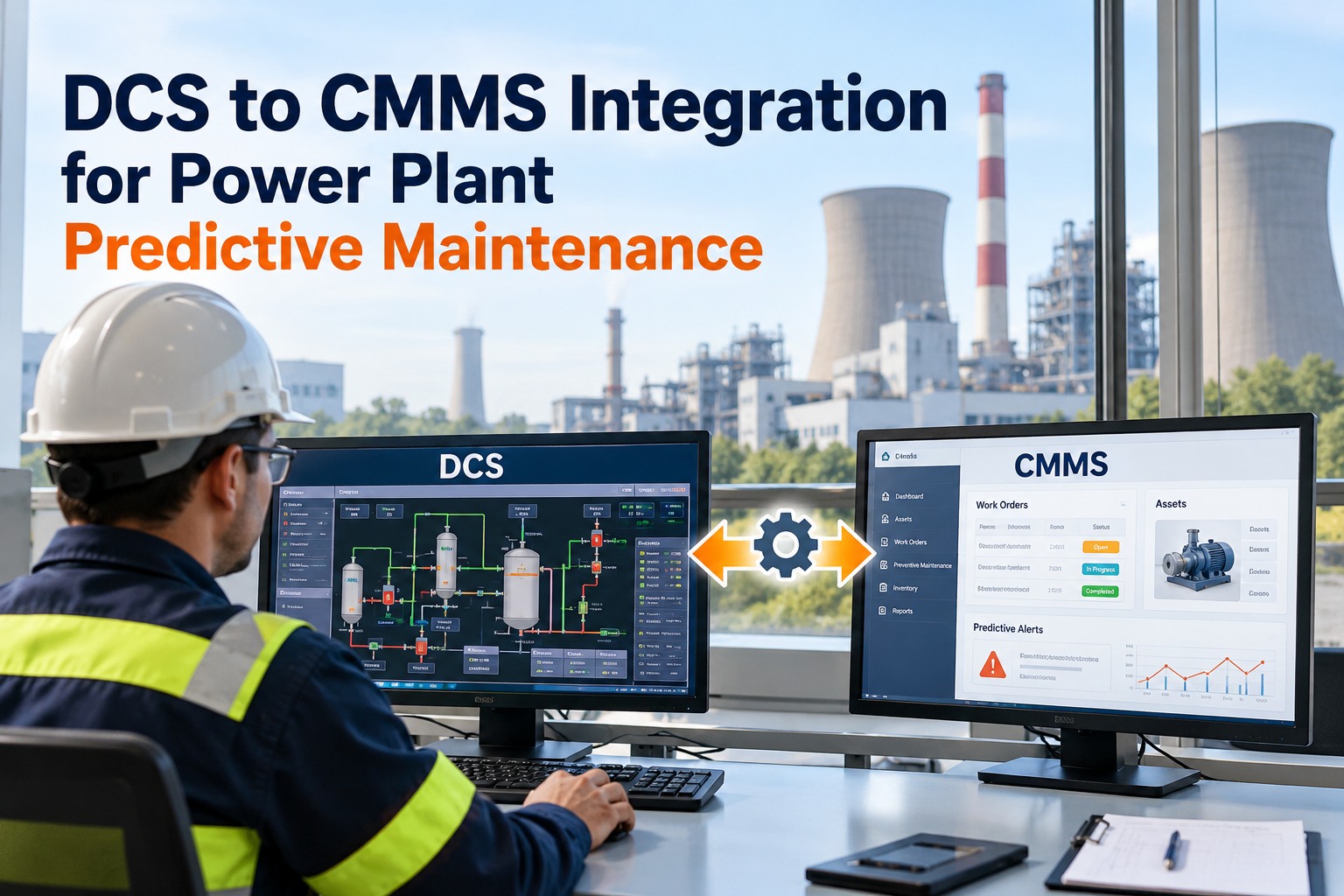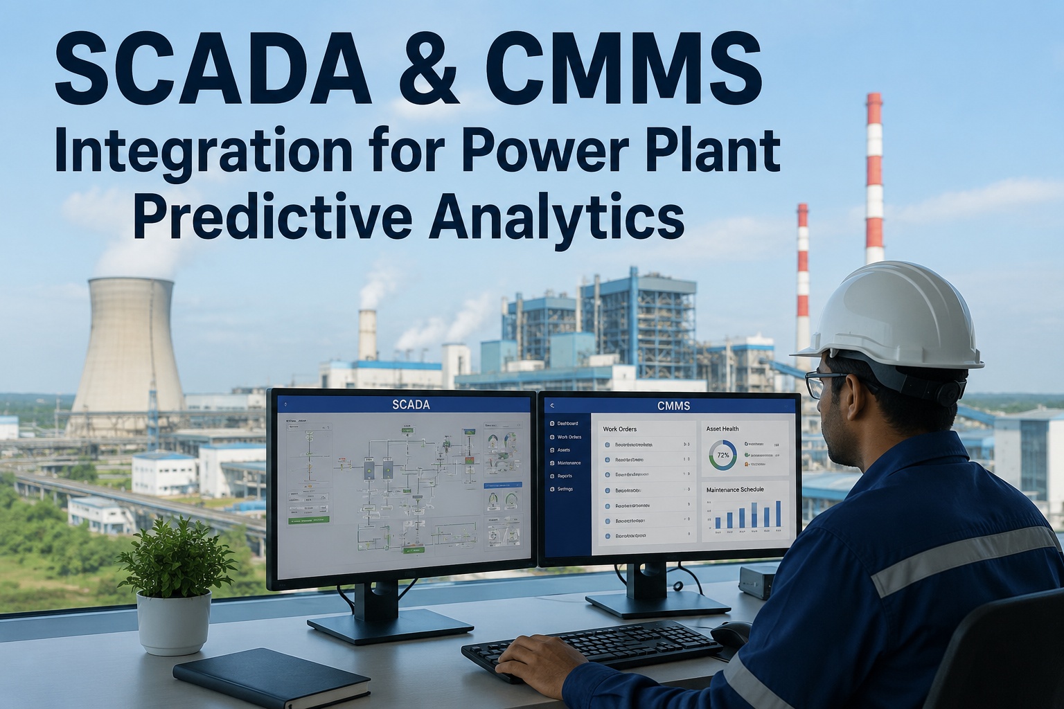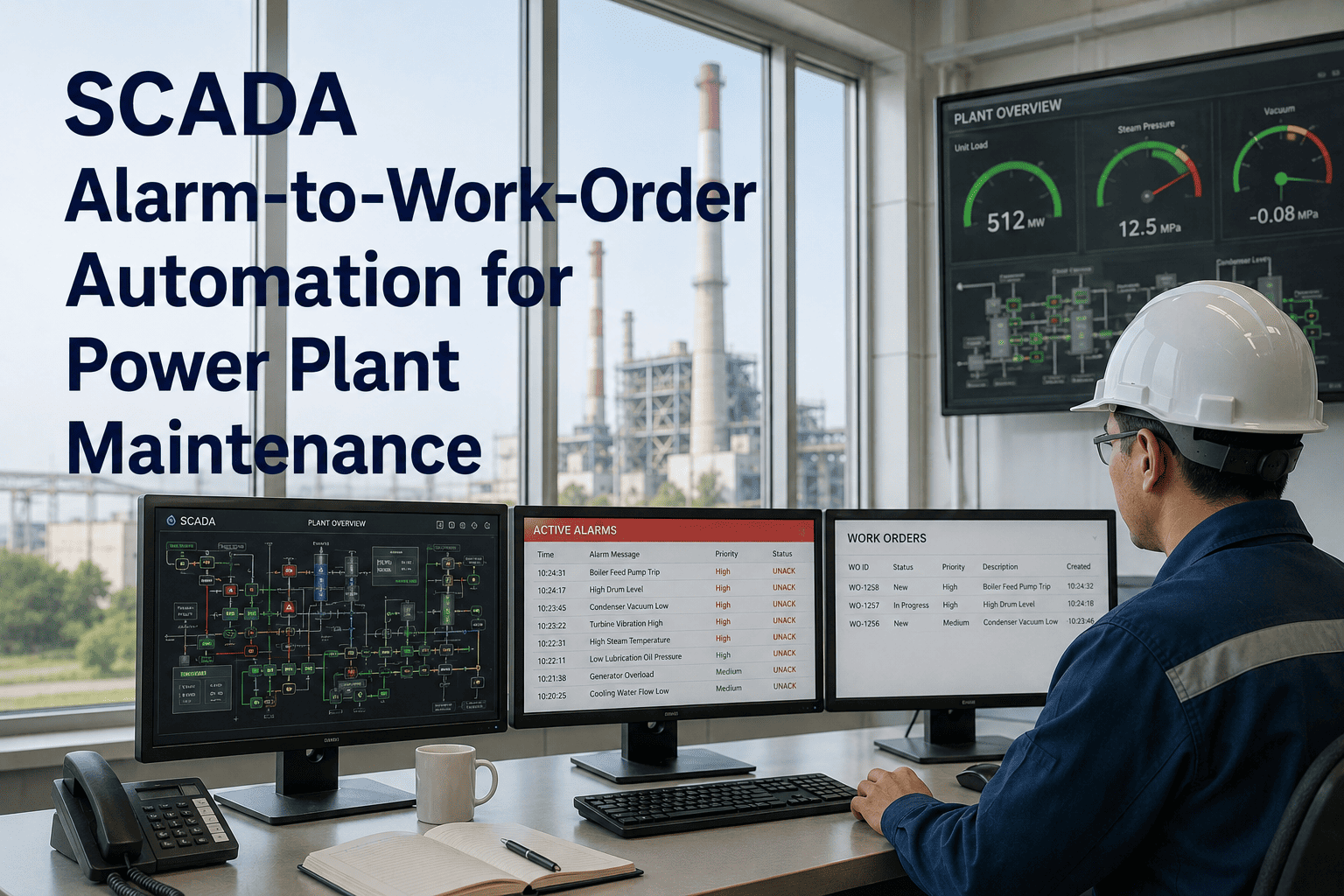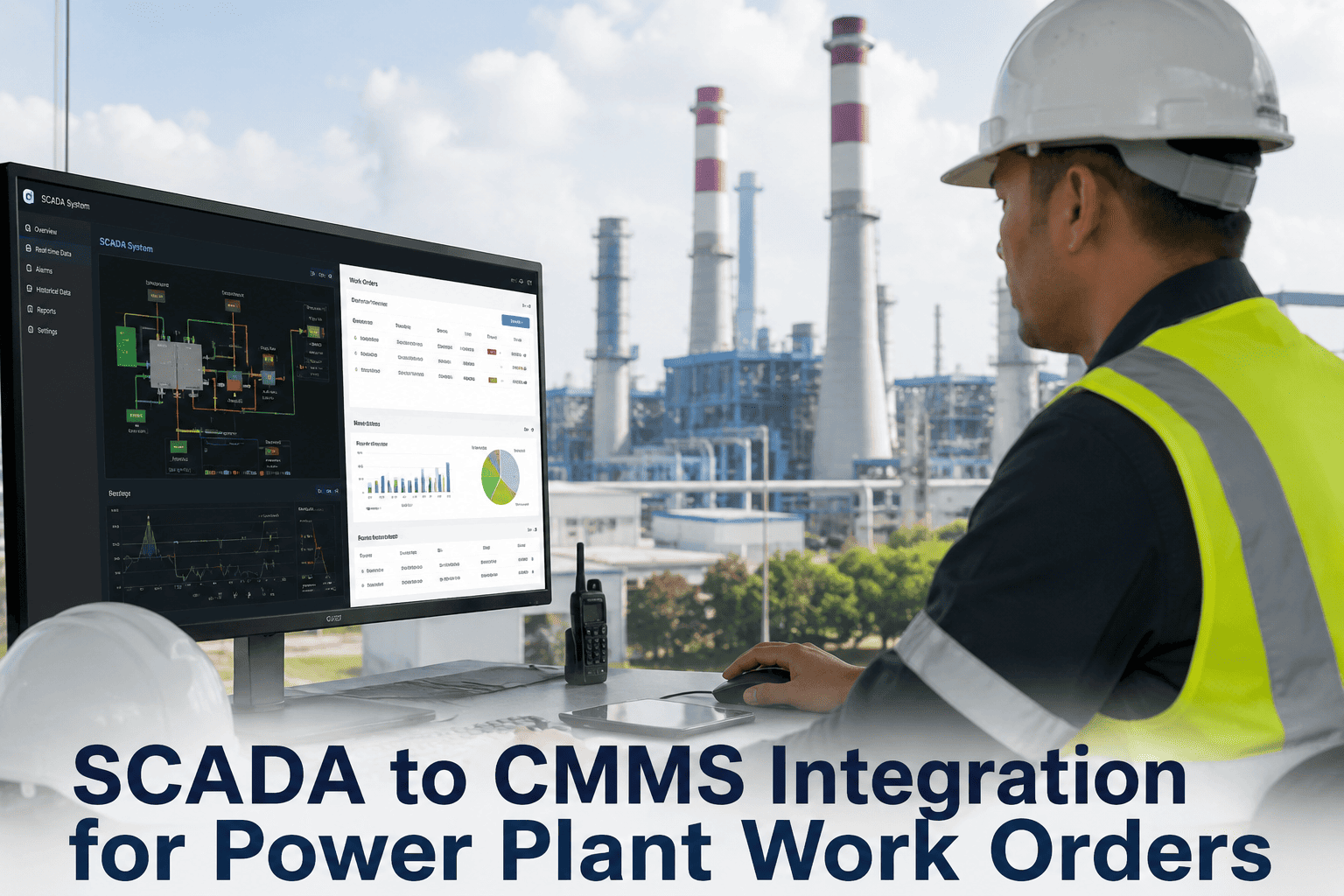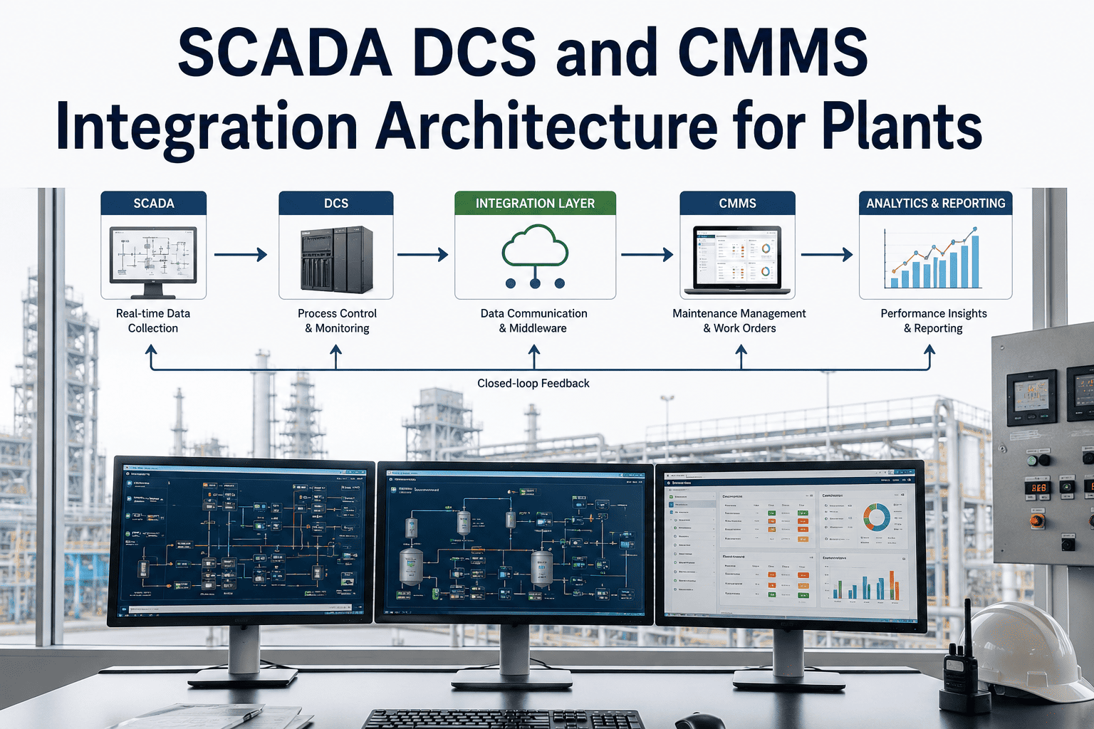
Inside every power plant are two separate universes that rarely speak to each other. The operational technology layer — SCADA, DCS, historians, and HMIs — sees everything, capturing every parameter deviation and fault code with millisecond precision. The information technology layer — your CMMS, ERP, and planning tools — acts on everything, managing every work order, spare part, and compliance record. The silence between them is where failures are born: an alarm fires at 6:47 a.m. in the DCS, and whether it ever becomes a work order depends entirely on a human noticing it, judging it important, and manually creating a record under operational pressure. That chain breaks constantly, and the cost is real — preventable alarms converting into forced outages that run into the millions per year at a single 500 MW facility. A well-designed SCADA, DCS, and CMMS integration architecture closes that gap permanently and safely. This guide walks through how that architecture is built, layer by layer, and you can start a free trial or book a demo to see it on your own systems.
SCADA, DCS and CMMS Integration Architecture for Plants
A practical architecture guide for connecting your control systems to maintenance management — safely, at the protocol layer, without touching control logic. Learn how OT data crosses to IT, how alarms become work orders in under 60 seconds, and how to design the integration so it produces intelligence, not noise.
The Two Universes and the Gap Between Them
Understanding the architecture starts with understanding why the problem exists. SCADA and DCS systems were built for real-time supervisory control and determinism — not for feeding maintenance analytics. Your CMMS was built to manage work — not to listen to a control network. They speak different data languages, run on different networks, and are operated by different teams with different objectives. Integration is the disciplined bridge between them.
Bridge the Gap Without Touching Your Control System
The single biggest fear in any OT/IT integration is risk to plant operations — and a correct architecture eliminates it by design. Oxmaint connects at the historian or OPC-UA layer as a read-only consumer with a unidirectional data path: there is no inbound command channel that could ever affect control. Your DCS logic, setpoints, and safety systems stay untouched, your OT team grants nothing more than read access, and the integration becomes additive rather than disruptive. That is the foundation everything else in this guide is built on.
How Data Crosses From the Plant Floor to a Work Order
A robust integration follows the Purdue model — the layered framework that segments industrial systems from the physical process up to enterprise IT. Data flows upward through defined zones, crossing the OT/IT boundary at a controlled point, never the reverse. Here is the full signal path, level by level.
Sensors and actuators (Level 0) feed PLCs and DCS controllers (Level 1). Raw signals — vibration, temperature, pressure, flow — arrive as 4-20mA, Modbus, HART, and Profibus. This layer stays fully isolated from the internet.
SCADA servers and DCS apply alarm thresholds, display real-time process state, and log every event with timestamp and tag ID. This is where operators watch the plant — and where alarms fire.
OSIsoft/AVEVA PI, Wonderware, or Ignition store time-series tag data — billions of points per day. The historian is the primary data source for trends and thresholds. The integration reads here; it does not bypass it.
A lightweight integration server in the iDMZ reads process values via read-only OPC-UA, applies filter rules, and publishes qualifying events. Data diodes and outbound-only connections make a reverse path architecturally impossible.
Receives structured payloads via REST API or MQTT, maps each tag to its asset, and auto-generates a work order with process values, priority, parts, and checklist attached — in under 60 seconds, no human in the loop.
Tag-to-Asset Mapping: Where Integrations Succeed or Fail
A raw DCS tag like GT1.BRG3.VIB.X means nothing to a maintenance planner until it is linked to a specific asset — Gas Turbine 1, Bearing 3, Vibration X-axis. Without clean mapping, sensor alarms have no asset context and produce noise instead of intelligence. A 500 MW plant carries 15,000 to 80,000 active tags, so disciplined filtering and mapping is the deliverable that determines whether the whole integration works.
Pull the full tag list from the historian — 15,000 to 80,000 active tags on a large plant.
Keep vibration, temperature, pressure, current, flow, and speed — typically just 5-15% of all tags.
Match each filtered tag to a specific equipment ID at the right location. Naming rarely matches; a cross-reference table is required.
Link each breach to a priority, craft, parts list, and checklist — Warning plans work; Critical dispatches it.
Start narrow: map 50-200 high-criticality tags covering your top 10-20 assets by failure impact — main turbine bearings, boiler feed pumps, generator windings, cooling water pumps. Mapping every tag from day one causes alarm flooding and low-quality work orders. Expand after the first 90 days once thresholds are validated.
Priority Tiers Stop Alarm Flooding From Becoming Work-Order Flooding
An integration that turns every alarm into a work order just moves the flooding problem downstream. The EEMUA-191 standard defines a manageable rate as under six alarms per operator per hour; plants above ten are overloaded, and critical alerts get missed. A three-tier priority structure, mapped to asset criticality, keeps the signal clean.
During an alarm storm — when one failure fires 200 cascading alarms in minutes — intelligent consolidation identifies the root cause, suppresses downstream effects, and creates a single prioritized work order with the correct troubleshooting sequence rather than overwhelming technicians with symptoms.
What to Demand From Any SCADA-CMMS Integration
Use this checklist to evaluate any integration architecture before deployment. Each row separates a safe, durable design from one that creates operational or security risk.
| Requirement | Safe Architecture |
|---|---|
| Data direction | Read-only, unidirectional OT to IT — no inbound command path |
| Control system impact | No DCS logic, setpoint, or safety system changes required |
| Network boundary | CMMS in the DMZ behind Purdue Level 3.5, never direct to OT |
| Protocol support | OPC-UA, OPC-DA, Modbus, MQTT, REST, historian API |
| Connectivity loss | Local edge buffer stores events and syncs when restored |
| Compliance | Immutable audit logs supporting NERC CIP evidence |
| Legacy DCS | OPC-DA wrappers, ODBC, or CSV polling for older platforms |
What a Correct Architecture Delivers
When the control room's intelligence becomes maintenance action automatically, the results compound across response time, recurring faults, and avoided outages. These reflect outcomes power plants report after deploying SCADA and DCS to CMMS integration.
Removing the manual escalation chain cuts the time from alarm to technician on-site by this much
Repeat alarm frequency on the same asset drops when every fault is documented with corrective action
Threshold breaches become assigned, context-rich work orders with no human in the loop
Preventable alarms left unactioned drive roughly this in forced-outage cost per 500 MW facility
Frequently Asked Questions
What is SCADA, DCS and CMMS integration architecture?+
Does this integration require changes to our DCS or control logic?+
Which protocols and platforms does Oxmaint support?+
How do you prevent alarm flooding from overwhelming technicians?+
How long does deployment take and where should we start?+
Turn Your Control Room Intelligence Into Maintenance Action
Your SCADA and DCS already see every developing failure with millisecond precision. The only question is whether that intelligence reaches your maintenance team in time to act — or dies in a historian nobody reads while a human is supposed to bridge the gap under pressure. Oxmaint connects to your DCS, SCADA, and historian as a read-only consumer, maps every tag to its asset, applies disciplined priority tiers, and converts threshold breaches into context-rich work orders in under 60 seconds. No control-system changes, no inbound command path, no alarm left unactioned. Build the architecture that closes the gap for good.