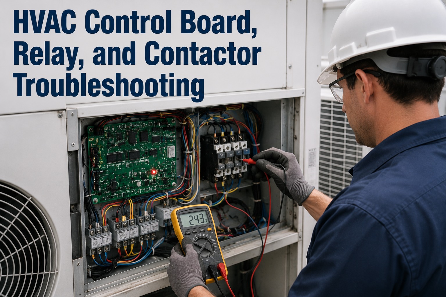
When an HVAC system goes dead but nothing is obviously burnt, the fault is almost always electrical — hiding in the control chain that carries a 24-volt thermostat call all the way to a compressor pulling forty amps. Control board, relay, and contactor are the three links in that chain, and a tech who can read the symptom back to the right link fixes it in one visit instead of guessing and coming back. This guide walks the electrical control chain the way a field technician works it: what each component does, how it fails, how to test it safely, and how CMMS fault history exposes the unit that keeps eating contactors. Start free or book a demo.
HVAC · Electrical Diagnostics · Board · Relay · Contactor · 2026
HVAC Control Board, Relay & Contactor Troubleshooting
Follow the electrical control chain from thermostat call to compressor, isolate the failed link, and stop the repeat callback — with fault history that shows why the same unit keeps failing.
24 VAC
control signal that switches a 40+ amp compressor load
<20 V
coil voltage that causes chattering and contact damage
2–3×
faster contactor wear on circuits reading under 208V
5–10 yr
contactor life — when the underlying fault is fixed
First rule, every time
These circuits carry line voltage that can injure or kill. Kill power at the breaker and the service disconnect, verify dead with a meter, and discharge capacitors before touching anything. Only test energized when a step explicitly requires it, meter rated for the voltage, insulated gloves on.
The Control Chain: One Call, Four Links
Every cooling cycle is a relay race. The thermostat sends a low-voltage call, the control board decides and sequences, a relay or the board switches the signal, the contactor throws the high-voltage load, and the compressor runs. When the unit won't start, the fault is somewhere along that chain — and the whole skill is isolating which link, not swapping parts until it works. Sign up free and OxMaint keeps each unit's electrical fault history on the asset, so you walk up already knowing which link failed last time.
24V
Thermostat Call
Low-voltage demand (R, C, Y, G, O/B) says "cool now."
→
PCB
Control Board
Reads the call, checks safeties, sequences and routes the output.
→
SW
Relay
Coil energizes, contacts close, passing the switched signal on.
→
L1/L2
Contactor
Coil pulls the armature in, line-voltage contacts feed the compressor.
The most common misdiagnosis is condemning the board when the fault is upstream — a bad transformer, a blown board fuse, low control voltage, or a tripped safety switch all mimic a dead board. Always rule out the simple links first.
Contactor: The Link That Fails Most
The contactor throws thousands of high-current arcs a season, so it wears fastest and fails most. Two failure modes dominate, and they point in opposite directions — one leaves the unit dead, the other won't let it stop. Book a demo to see contactor replacements logged per unit, so a second failure in a season flags a root cause instead of a routine swap.
Won't pull in
Pitted / Open Contacts or Burnt Coil
Indoor blower runs but the outdoor compressor and fan stay silent. Arcing has pitted the contact faces into high resistance, or the coil has burned open and can't close the contacts at all.
TestCoil resistance across coil terminals (open = burnt); contact continuity with coil energized — no/erratic continuity = replace
Won't drop out
Welded Contacts
The outdoor unit keeps running after the thermostat is satisfied — a high-amperage arc melted the contacts together. Dangerous: it can freeze the coil or cook the compressor.
TestPower off, wires off: near-zero ohms across contacts that should be open = welded shut = replace immediately
Buzzes / chatters
Chattering (the early warning)
A buzzing or rapid-fire clicking instead of a clean "thunk" means the coil can't hold the armature in — it's rapidly engaging and releasing, pitting the contacts with every cycle. Left alone, it welds or burns them.
TestMeter coil voltage while running — below 20 VAC (normal 22–26) is the cause, not the contactor itself
Don't just swap it — ask why
A contactor that dies twice in a season is a symptom. The real cause is usually upstream: low voltage, an oversized load, insect nests bridging contacts, or a control-voltage sag. Fix that and the replacement lasts 5–10 years.
Why the Same Unit Keeps Eating Contactors
Repeat contactor failure is the classic "callback that keeps coming back," and it's almost never bad luck. Four root causes account for most of it — and each is fixable once you stop replacing the victim and find the driver. Sign up free and log each replacement with its cause, so the pattern across three visits becomes obvious instead of invisible.
01
Undervoltage at the Load
Low line voltage makes the compressor draw higher amps, so each closing arc is bigger. Units consistently under 208V on a 230V system burn contactors 2–3× faster.
02
Oversized or Mismatched Rating
A contactor rated below the equipment's actual nameplate FLA is destroyed from day one. Always match the amp rating to the nameplate — not to the old contactor that already failed.
03
Short Cycling / High Cycle Rate
Every cycle is an arc event. A compressor cycling 10–15 times an hour pits contacts fast regardless of load. Chase the cycling cause — sizing, charge, or controls.
04
Control-Voltage Sag & Chatter
A weak transformer or damaged low-voltage wiring drops coil voltage under load, causing chatter. A 40VA transformer sagging under coil current is a common hidden culprit.
The Third Contactor in Eight Months Isn't a Contactor Problem. It's a Records Problem.
When each failure is a separate ticket in a separate tech's memory, nobody sees the pattern — so the fix is always "replace the contactor" and the unit keeps failing. The moment those three visits live on one asset record with the cause noted each time, the real story appears: the circuit reads 201V under load, or the transformer sags, or the unit short-cycles. OxMaint keeps every electrical fault, part swap and reading on the unit, so the repeat offender surfaces itself.
Relay & Control Board: Reading the Signals
If the contactor tests good, the fault moves upstream to the relay and the board. Relays fail much like contactors in miniature — stuck, open, or chattering — while the board is the most misdiagnosed part in the whole system. The trick is proving whether the board is actually bad or just reporting an upstream fault. Book a demo to see board fault codes and relay swaps recorded per unit so recurring board symptoms trace to their real source.
Relay Won't Switch
Board gets the thermostat call but the component never energizes. Test relay coil resistance and contact continuity; a stuck or open relay mimics a dead board but replaces separately on many models.
Blower Runs Continuously
The fan or heat relay is stuck closed — a welded contact or failed relay driver. Confirm it's not the thermostat in "fan on" first, then test the relay before condemning the board.
LED Fault Codes
Most boards since 2000 flash a code (e.g. 3 flashes = pressure switch). The code usually points upstream — a tripped limit, pressure switch or flame sensor — not to a bad board. Read it before you replace anything.
No LED, No Outputs
Board dark and nothing powered? Check the board fuse and the 24V transformer secondary first. Low or no 24VAC means transformer or primary power, not the board.
Output Present, Component Dead
If the board outputs correct voltage at the terminal but the part doesn't run, the fault is downstream — the motor, capacitor, or contactor — not the board. Meter the output to prove it.
Intermittent / Vibration-Linked
Runs sometimes, drops out others, often with heat or vibration. Tap-test relays with a plastic handle; intermittent operation suggests a loose solder joint or cracked trace.
The Diagnostic Sequence That Isolates the Link
Working the chain in order — cheapest and most upstream first — is what turns a guessing game into a clean diagnosis. This is the sequence that isolates the failed link without throwing parts at it. Sign up free and turn this into a standard work order checklist every tech follows, with readings captured against the unit.
1
Lock out & verify dead
Breaker and disconnect off, meter-confirm zero voltage, discharge capacitors.
2
Visual first
Look for burnt terminals, bulging caps, melted connectors, insect nests, scorched traces.
3
Confirm the call & the 24V
Verify the thermostat sends the demand and R-to-C reads ~24VAC at the board.
4
Check board power & fuse
Board fuse intact, transformer secondary at spec, LED lit and reading any code.
5
Meter the board output
On a call, is the correct voltage present at the output terminal? Present = look downstream.
6
Test relay coil & contacts
Coil resistance in spec, contacts close on energize. Stuck or open = replace the relay.
7
Test the contactor
Coil resistance, contact continuity, and coil voltage under load for chatter.
8
Find the driver, log it
Measure supply voltage and amp draw, note the root cause, record it on the asset.
One-Off Tickets vs. Fault History in OxMaint
The difference between fixing a symptom and fixing a unit is whether the last three visits are visible when the fourth one starts. Here's what changes when electrical fault history lives on the asset. Start free and put your first unit's electrical history on record this week.
What OxMaint's Maintenance Software Does for Electrical Diagnostics
Electrical faults are pattern problems as much as component problems, and patterns only show up when the history is in one place. That's what a CMMS gives the field. Here's the concrete mapping. Book a demo to see it against your equipment.
Per-Unit Fault History
Every board fault, relay swap and contactor replacement logs against the specific unit — so the tech on visit four sees visits one through three before opening the panel.
Root-Cause Capture
Record the driver, not just the part — the 201V supply, the sagging transformer, the short cycling — so repeat failures get fixed at the source instead of re-swapped.
Standard Diagnostic Checklist
Turn the isolate-the-link sequence into a work-order template every tech follows, so the upstream checks happen before anyone condemns a board.
Numeric Readings Trended
Capture supply voltage, coil voltage and amp draw as numbers per visit, so a slow voltage sag or rising draw shows as a trend, not a surprise.
Nameplate & Part Specs
Store equipment FLA and correct coil voltage on the asset, so the right-rated contactor gets ordered instead of matching the failed one.
Repeat-Offender Dashboard
See which units keep generating electrical calls across the whole fleet, so the chronic ones get a root-cause visit instead of another band-aid swap.
OxMaint doesn't hold the meter — it holds the memory, so the diagnosis you make today is there for the next tech and the pattern you can't see in one visit becomes obvious across three. Sign up free and start logging electrical faults this week, or book a demo to walk it against your equipment.
"
We had a rooftop unit that went through four contactors in one cooling season, and every ticket just said "replaced contactor, unit running." Three different techs, none of them saw the others' visits. When we moved to OxMaint and started logging the cause, the second tech to open it saw the history and metered the supply — 203 volts under load on a 230 line. It was never a contactor problem; it was a utility voltage issue we chased down with the power company. Now every electrical fault carries its readings and its cause on the unit, and our repeat callbacks on control faults dropped off a cliff. The parts were never the problem — not having the history was.
Service Manager · Commercial HVAC Contractor
Frequently Asked Questions
How do I tell a bad contactor from a bad control board?
Work upstream to down. Confirm the 24V call reaches the board, meter the board output on a call — if correct voltage is present but the part doesn't run, the fault is downstream at the relay, contactor or motor, not the board.
What does a chattering contactor mean?
The coil can't hold the armature in, so it rapidly opens and closes — pitting the contacts each time. It's almost always low coil voltage (under 20 VAC), not the contactor itself. Fix the voltage or it welds next.
Why does the same unit keep destroying contactors?
Repeat failure points to a root cause: undervoltage at the load, an under-rated contactor, short cycling, or a sagging control transformer. Replacing the contactor without finding the driver just resets the clock.
How do I test a contactor with a multimeter?
Power off, wires disconnected: measure coil resistance across the coil terminals (open = burnt coil), and check contact continuity — near-zero ohms across contacts that should be open means they're welded shut.
The board shows an LED fault code — is the board bad?
Usually not. Fault codes typically point upstream to a tripped safety — limit switch, pressure switch or flame sensor. Read the flash sequence against the wiring diagram and check that component before replacing the board.
How does a CMMS help with electrical troubleshooting?
It keeps every fault, reading and part swap on the unit, so repeat failures and their root causes are visible across visits and techs instead of lost in one-off tickets.
Sign up free to set it up.
Fix the Unit, Not Just the Contactor.
OxMaint keeps every electrical fault, reading and part swap on the asset, standardizes the diagnostic sequence as a work-order checklist, and surfaces the units that keep failing — so the root cause gets found instead of the contactor getting re-swapped. Start free — no credit card, unlimited users, forever. Or book a demo for a walkthrough on your equipment.