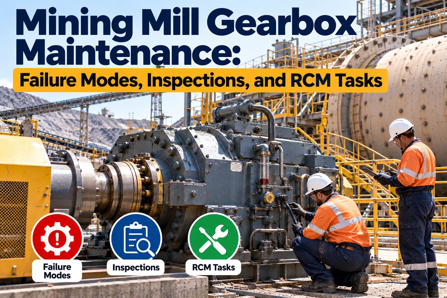
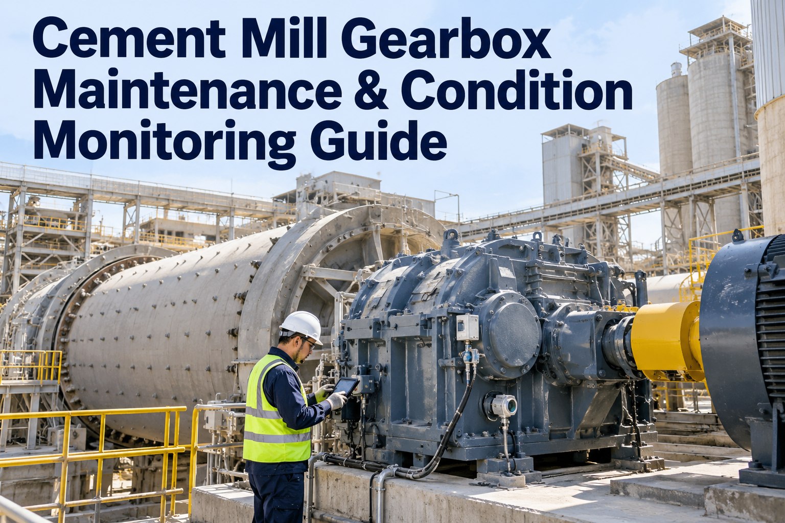
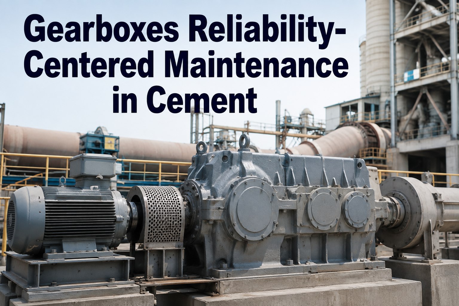
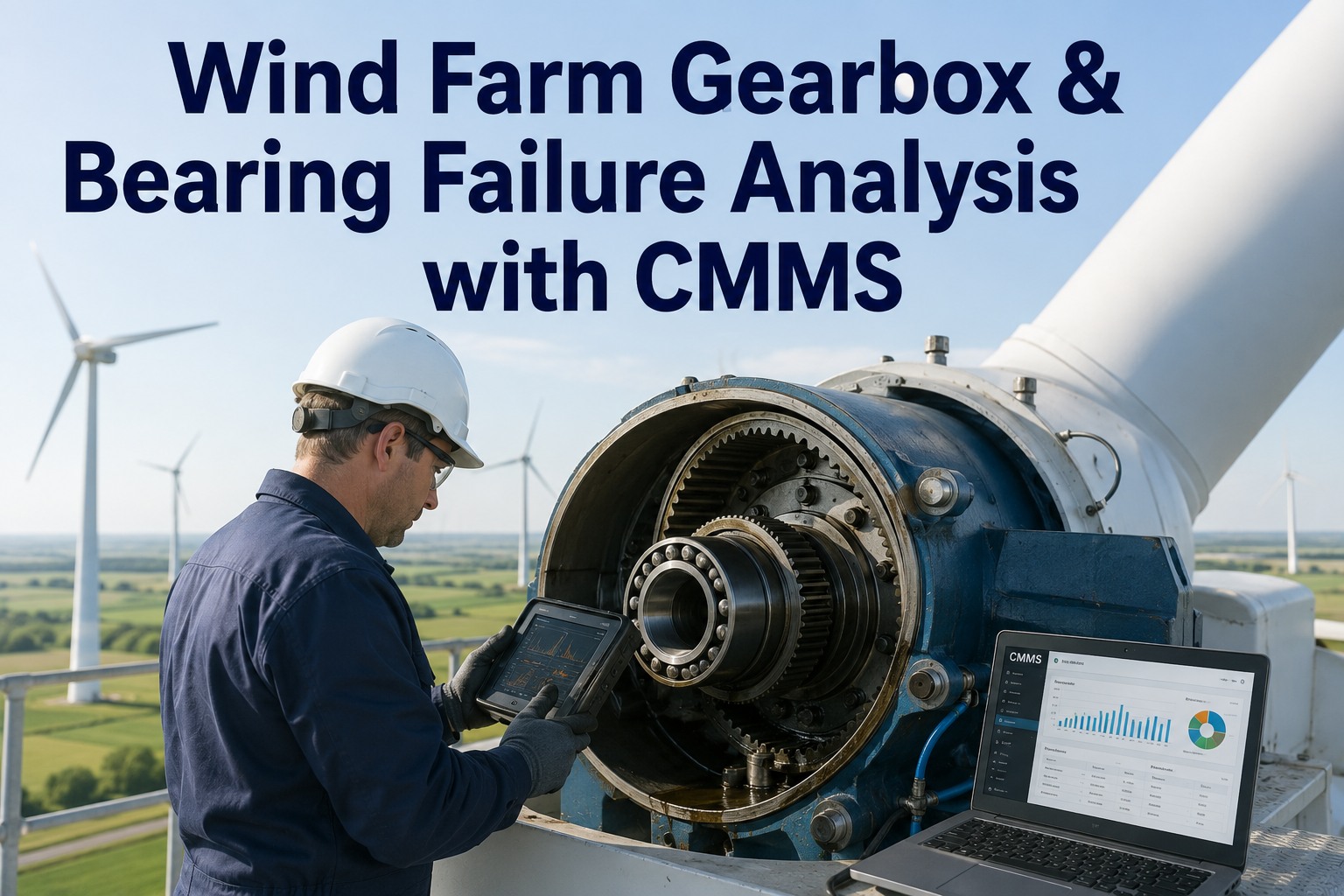
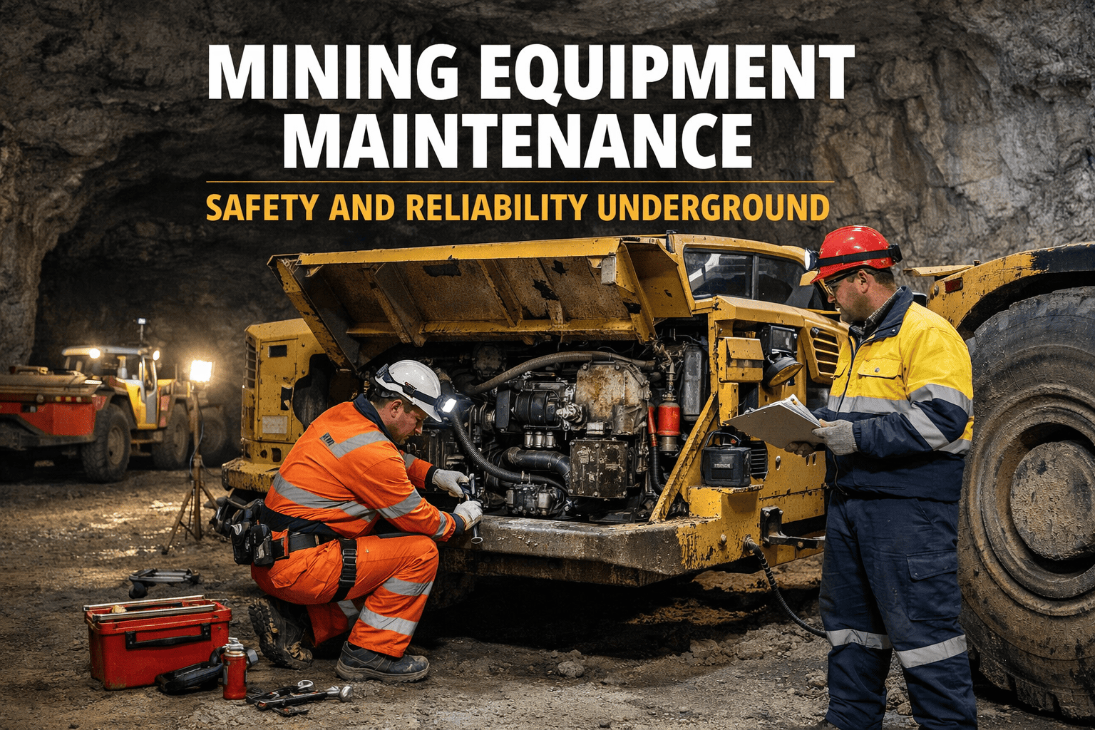
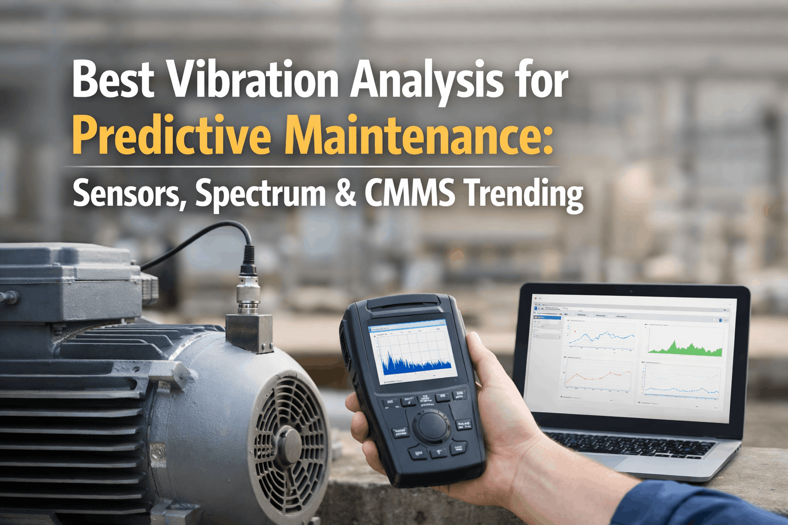
At 02:00, rising gearbox vibration and darkening oil are not reasons to wait for day shift. The mill is carrying the production plan, and the crew needs a defensible call: damaged mesh, failing bearing, normal response to harder ore, or a lubrication-system problem? Continue, derate, make a controlled stop, or trip now? Oxmaint AI connects vibration, oil, temperature, lubrication performance, events, inspections, and work history into one governed timeline and drafts an evidence-backed work order inside the existing Maximo, SAP, or CMMS workflow.
Mining Mills · RCM Overlay · Gearbox PdM · 2026
Mining Mill Gearbox Maintenance: Signal to Governed Decision
Oxmaint AI is an AI RCM overlay on Maximo, SAP, Infor, or your CMMS — it separates changing load and speed from developing damage, ranks failure hypotheses, and drafts a planner-ready work order. Not a second system of record.
1 Timeline
historian, vibration, oil, inspection & EAM aligned
6 Modes
failure modes drive the planner queue
5 Signals
evidence families fused per diagnosis
90 Days
pilot the overlay without replacing systems
Confirm the Analysis Boundary First
A ring-geared mill may have one or two motor-reducer-pinion trains; a central drive has different load paths; a gearless mill has no main gearbox at all. Installed limits stay specific to the mill, gearbox, lubricant, torsional design, and OEM documentation — ISO 6336, AGMA, ISO 4406, and ISO 20816 inform the basis but don't replace them. Start free on your current stack — no rip-and-replace.
"High Vibration" Alone
The Way It Fails
✕ One alarm turned into "gearbox bad"
✕ Higher mesh amplitude blamed, not throughput
✕ Oil color read as a diagnosis
✕ Gears replaced without correcting geometry
✕ Healthy display assumed to prove protection
✕ One fleet-wide limit ignores the installed unit
✕ The drive becomes the outage
Oxmaint AI Overlay
The Way It Works
✓ Uncertainty preserved, hypotheses ranked
✓ Vibration normalized to load & speed
✓ Oil tracked by cleanliness, water & wear morphology
✓ Misalignment separated before gears are pulled
✓ Protection paths proof-tested, not assumed
✓ Limits read from the installed-unit manual
✓ Ranked WO drafts pushed into Maximo/SAP
What One Governed Timeline Shows
Oxmaint AI aligns years of historian, vibration, oil, inspection, and CMMS records into one governed asset timeline. That context changes the decision, and every item stays traceable to its source. Book a demo to see one mill drive's timeline live.
02:14 → 02:22
The Deviation
02:14 gear-mesh sidebands exceed the load-normalized baseline; 02:22 oil return temperature rises while mill load stays stable. Latest sample: coarse ferrous particles trending upward.
Prior Work
History Context
Prior work: filter replaced, but no contamination root cause recorded. Earlier outage: coupling disturbed and cold alignment completed without a documented hot-state check.
Interpretation
Weighted Evidence
Stable motor load weakens a process-overload-only explanation. Repeating mesh sidebands plus ferrous debris strengthen the case for active gear distress. A recent lubrication or alignment event may explain onset.
Confidence
74% Example
An illustrative 74% confidence in progressive gear-surface distress is not a measured probability or an autonomous stop instruction — it's a prompt to validate evidence, retain alternatives, and define the next safe task.
Overlay Positioning — Not a Second CMMS.
Asset masters, cost centers, inventory, and settlements stay in your EAM. Oxmaint AI owns living failure-mode history, JA1011-style task selection, and ranked WO drafts that push into Maximo or SAP. Source records and final approvals remain governed in the site system.
Failure Modes That Drive the Planner Queue
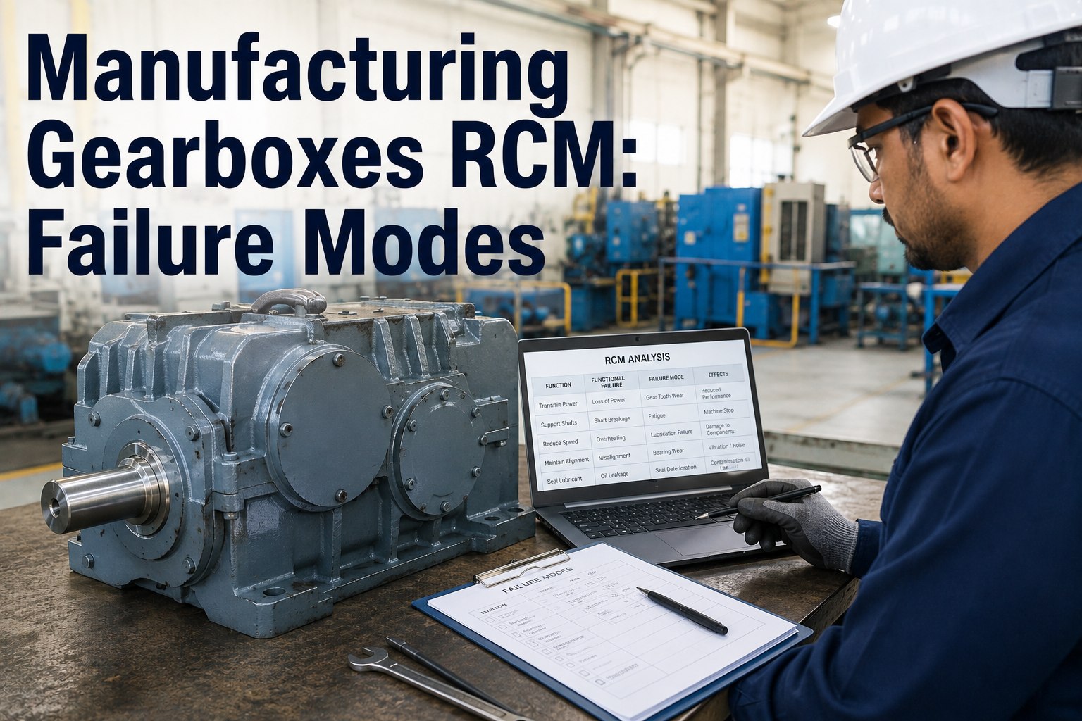
RCM begins with required functions: transmit torque, support shafts, maintain mesh geometry, distribute lubricant, exclude contamination, and provide effective alarms and trips. The queue should reflect failed functions and consequences — not just "high vibration." Book a demo to map these six modes to your queue.
RCM Task Intervals — PdM / PM / FF
Intervals should come from consequence, exposure, detectable degradation, OEM limits, and evidence on the installed unit — not a generic calendar. Corrective work begins when evidence crosses site-approved run, derate, controlled-stop, or immediate-stop criteria. Sign up free and set intervals from your P-F evidence.
Signals Oxmaint AI Weights on Your Tags
Vibration analysis is strongest fused with operating and lubricant evidence. These are illustrative configuration values, not universal limits. Oxmaint AI learns the useful comparison state for your tags — speed, load, mode, ore conditions, ambient, thermal lag, and recent maintenance. Book a demo to see the weighting on your tags.
28%
Order-tracked vibration and waveform evidence
24%
Oil chemistry, cleanliness and wear debris
20%
Lubrication pressure, flow, filter and thermal performance
16%
Load, speed, starts, trips and torque events
12%
Inspection, alignment, foundation and work history
Diagnostic forks matter. High return temperature with restricted flow supports an oil-system issue; temperature rising only with load points to process demand. Water after rainfall or washdown points to ingress; water rising independent of weather may justify cooler isolation or pressure testing.
Overlay Flow: Ingest → Detect → Diagnose → Prioritize → Dispatch
The flow preserves engineering judgment and CMMS governance at every step. Priority applies consequence and recurrence — production dependency, exposure, redundancy, progression rate, restart risk, and independent-evidence confidence. Sign up free and run the flow on one mill drive.
01
Ingest
Connect historian tags, vibration systems, lab results, inspection records, operator observations & governed Maximo/SAP/Infor/CMMS history.
02
Detect
Normalize by speed, load & mode. Identify sustained deviations, repeating impacts, changing sidebands, thermal drift, contamination trends, abnormal starts & ineffective protection channels.
03
Diagnose
Rank gear distress, bearing damage, contamination, misalignment, torsional damage & lubrication-protection failure. Show evidence for and against each — not one collapsed label.
04
Prioritize
Apply consequence & recurrence: production dependency, personnel/environmental exposure, redundancy, progression rate, restart risk, repeated events & outage window.
05
Dispatch
Prepare an approved draft WO in the existing EAM with trends, sample identity, decision criteria, task plans, safety notes & failure-code recommendations. Approvals stay governed.
Planner-Ready Work Order Fields
A useful work order carries ranked evidence, not a verdict. Do not open covers or defeat interlocks on an energized train unless an approved engineered procedure explicitly permits it. Book a demo to see a drafted mill-drive work order.
01
Problem: Asset position, operating mode, speed, load, alarm state, vibration points, oil sample identity, temperatures & observation time.
02
Cause hypotheses: Ranked mechanisms with evidence for and against gear distress, bearing damage, contamination, misalignment, torsional damage or protection failure.
03
Failure code: Site hierarchy for component, functional failure, mechanism & cause — e.g. GEARBOX / TORQUE-TRANSMISSION-DEGRADED / GEAR-SURFACE-DISTRESS / CONTAMINATION-OR-LOAD-DISTRIBUTION.
04
Tasks: Confirm vibration under comparable load, collect synchronized oil-system data, take a representative sample, preserve filter or magnetic-plug evidence & inspect accessible foundations, breathers, leaks, guards & coupling indicators.
05
Decision threshold: State what triggers continued monitoring, derating, borescope scope, controlled shutdown, or immediate escalation.
06
Parts hints: Verified lubricant, filters, breathers, seals, sample hardware, inspection-cover gaskets, locking devices & configuration-matched bearing or coupling kits.
07
Safety controls: Lockout/tagout, stored rotational energy, hot oil, line breaking, work at height, lifting, spill control, fire exposure & restricted access.
08
Completion findings: As-found condition, measurements, images, parts used, root-cause evidence, post-work baseline & recommended interval revision.
90-Day Pilot on Your Stack — Overlay, Not Rip-and-Replace
Start with one production-critical geared mill. Any downtime, repair, labor, parts, or production-loss values used must be labeled illustrative and replaced with site-approved costs. No savings or ROI claim is implied. Sign up free and pilot one critical mill drive.
Days 1–30 · Scope
Confirm asset boundaries, architecture, tag quality, failure modes, criticality, existing alarms, sample points & CMMS history.
Days 1–30 · Frame
Build a JA1011-style framing of functions, functional failures, consequences & feasible tasks — without claiming a certified study.
Days 31–60 · Baseline
Establish load- and speed-normalized baselines; connect vibration, oil, lubrication, operating-event, inspection & work-history evidence.
Days 31–60 · Validate Forks
Validate diagnostic forks with maintainers, analysts, operations & engineering.
Days 61–90 · Run Workflow
Run the governed workflow from detection through approved EAM dispatch.
Days 61–90 · Test Records
Test draft work orders, proof-test task records, evidence links, failure codes, completion feedback & escalation criteria.
"
At 02:00, rising gearbox vibration and darkening oil weren't reasons to wait for day shift — the mill was carrying the production plan and we needed a defensible call. Stable motor load weakened a process-overload explanation, while repeating mesh sidebands plus ferrous debris strengthened the case for active gear distress. Having that whole context on one timeline is what let us decide to continue, derate, or stop with confidence instead of guessing.
Millwright Lead · Concentrator Operations
Frequently Asked Questions
What should a mining mill gearbox maintenance program monitor first?
Start with configuration, consequence, and operating context. For a critical geared mill, monitor load- and speed-referenced vibration, lubricant cleanliness and debris, oil pressure and flow, bearing and oil temperatures, starts, trips, and repeatable visual findings.
How often should mill gearbox oil be sampled?
There is no universal interval. Base it on criticality, oil volume, environment, sample quality, duty, history, and degradation rate. Sample sooner after water ingress, filter bypass, cooler problems, abnormal wear, or an oil change.
Does high gear-mesh vibration require an immediate stop?
Not by itself. Validate the sensor, load, speed, spectrum, sidebands, waveform, temperature, debris, and rate of change. Use predefined, asset-specific stop criteria and independent evidence.
How does Oxmaint AI work with Maximo, SAP, Infor, or another CMMS?
Oxmaint AI overlays the existing EAM. It correlates condition and operating evidence with governed history, ranks failure hypotheses, proposes consequence-based work, and sends an approved draft into the current workflow.
Map One Critical Mill Drive Before Scaling the Fleet.
Turn gearbox signals into a governed maintenance decision on the CMMS you already use. Start free to build a governed mill drive workflow — without replacing your system of record.