Gas Conditioning Tower Maintenance and Spray Nozzle Programs

By Johnson on June 6, 2026

gas-conditioning-tower-maintenance-spray-nozzle-programs

The gas conditioning tower sits between the preheater and the electrostatic precipitator — and when it fails, neither system works correctly. Hot gas entering the GCT at up to 400°C must be cooled to 120–180°C through evaporative water injection before reaching the ESP, where particulate collection efficiency depends critically on gas temperature and moisture content. A single failed spray nozzle in a 33-nozzle GCT reduces cooling capacity and destabilizes ESP performance within hours. A blocked water supply line or failed pump trips the cooling system entirely — either forcing an emergency kiln slowdown or driving ESP inlet temperatures above the design limit, where precipitator damage and emission exceedances follow rapidly. Despite this criticality, GCT spray nozzle programs remain among the most poorly documented PM activities in cement plant CMMS records — inspections happen reactively, nozzle wear data is never trended, and water pump condition is monitored only after cavitation symptoms appear. Sign up free on OxMaint to build a structured GCT PM program with nozzle condition tracking, water pump monitoring, control valve calibration scheduling, and the outlet temperature trending that catches performance degradation before it reaches the ESP.

Cement Plant Emission Control

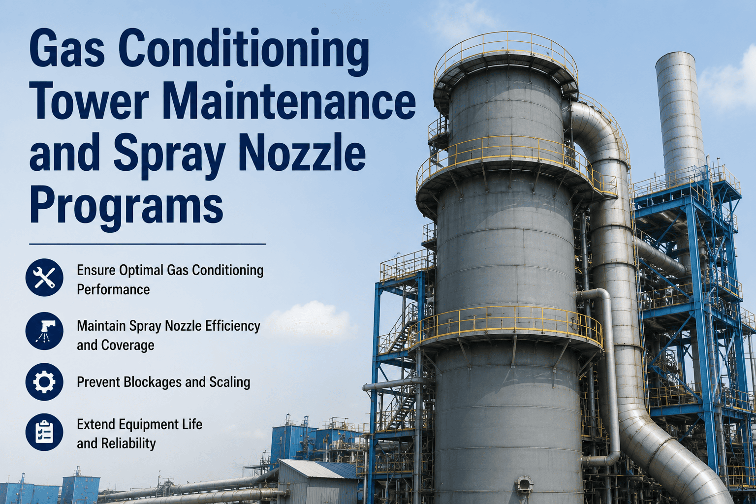
Gas Conditioning Tower Maintenance: The System Between Your Kiln and Your Compliance Record

A failed GCT nozzle or water pump does not just reduce cooling efficiency — it sends out-of-range gas directly to your ESP, risking emission exceedances, permit violations, and precipitator hardware damage that takes weeks to repair.

Preheater Exit Gas
Up to 400°C
Gas Conditioning Tower
Spray Nozzles
Water Pump
Control Valves
Temperature Sensors
ESP Inlet Gas
Target: 120–180°C

Four GCT Components — Four Failure Modes That Reach the ESP

N
Spray Nozzles
Two-fluid nozzles atomize water into fine droplets using compressed air. Nozzle orifice wear enlarges the droplet size over time — large droplets do not fully evaporate before reaching the tower bottom, creating wet dust accumulation and potential ESP inlet moisture problems.
Orifice wear Larger droplets, incomplete evaporation
Nozzle plugging Reduced cooling capacity, hot gas to ESP
Lance misalignment Uneven spray distribution, wall wetting
PM: Nozzle flow test and dimensional check every 2,000 hours — plugged nozzles replaced, worn orifices reamed or swapped
P
Water Supply Pump
High-pressure water pumps supply filtered water at controlled pressure and flow to the nozzle header. Pump degradation reduces delivery pressure below the atomization threshold — degrading spray quality before flow alarms trigger. A secondary pump should be available; both require condition monitoring.
Impeller wear Reduced delivery pressure, poor atomization
Seal failure Water leak, motor overheating
Filter plugging Pressure drop, cavitation onset
PM: Bearing vibration and motor current logging monthly — delivery pressure test quarterly — filter element replacement per differential pressure threshold
V
Control Valves
Proportional control valves regulate water and compressed air flow to the nozzle headers based on outlet temperature feedback from the control system. Valve seat wear or actuator calibration drift allows gas temperature to exceed the setpoint even when the control logic is commanding the correct output — making the system appear to work while failing silently.
Valve seat wear Flow does not match commanded position
Actuator drift Temperature control instability
Positioner failure Fixed output, no temperature response
PM: Full stroke actuator test and positioner calibration check every 6 months — valve trim inspection during annual shutdown
T
Temperature Sensors
Inlet and outlet temperature sensors drive the GCT control logic. A drifted or failed outlet thermocouple sends incorrect feedback to the controller — potentially commanding reduced water flow while actual gas temperature is already exceeding the ESP design limit. Redundant sensor comparison is the only reliable detection method.
Thermocouple drift Incorrect setpoint control, hot gas to ESP
Sensor fouling Slow temperature response, late control action
Transmitter failure Control system reverts to default flow mode
PM: Sensor comparison check monthly — thermocouple calibration verification quarterly — transmitter loop test every 6 months

GCT Performance KPIs: What Your CMMS Should Track and Why

Outlet Temperature Deviation from Setpoint
Target: Within ±10°C of control setpoint
Trending deviation more than 10°C above setpoint: nozzle plugging or pump pressure loss. Deviation below: water overinjection risk — wall wetting and wet dust accumulation at tower base.
Water Consumption vs Cooling Load
Target: Baseline water L/min per 100°C cooling achieved
Rising water consumption for the same temperature drop indicates nozzle wear enlarging orifices. Falling consumption with increasing outlet temperature indicates nozzle plugging or valve restriction.
Pump Delivery Pressure
Target: Within 5% of design delivery pressure
Progressive pressure drop over weeks indicates impeller wear or filter plugging. Sudden pressure loss indicates seal failure or filter blockage. Daily logging catches gradual degradation that vibration monitoring alone cannot detect.
Tower Bottom Wet Dust Accumulation Rate
Target: Stable or declining accumulation between planned cleanouts
Increasing accumulation rate indicates incomplete droplet evaporation — caused by oversized nozzle orifices, low gas flow velocity, or excessive water injection relative to gas temperature. Triggers nozzle inspection work order.
A 20% reduction in GCT water consumption was achieved at one cement facility through nozzle count optimization and control valve calibration — while maintaining outlet temperature within specification. Every liter of water not evaporated in the GCT is a liter that must be processed by the ESP and downstream dust handling system. Nozzle PM is not just an equipment reliability question — it directly affects your plant's water budget and downstream equipment load.

GCT Shutdown Inspection Checklist — What Gets Done at Every Planned Outage

Interior Inspection
Tower shell interior — refractory or liner condition at inlet section
Spray nozzle lance position and alignment verification per nozzle
Nozzle orifice visual inspection — erosion, deposits, deformation
Tower base wet dust accumulation measurement and cleanout
Internal access door seal condition and bolt torque check
Lower conical section for wire mesh screen buildup (where installed)
Water System
Water pump impeller clearance check and seal inspection
Double filtration system — element replacement per DP threshold
Supply line strainer cleanout and inspection
Pump motor insulation resistance check
Standby pump operational test — delivery pressure verification
Water quality check — suspended solids, hardness level trending
Control and Instrumentation
Outlet temperature sensor calibration check against reference
Control valve full stroke test and positioner calibration
Compressed air supply pressure — nozzle atomizing air valve test
Temperature control loop response test — setpoint ramp test
All instrument tags physically verified and labeling confirmed
DCS alarm setpoint verification — high and low temperature alert values

A Well-Maintained GCT Is Invisible. A Failed One Shuts Down Your ESP.

OxMaint gives cement maintenance teams a structured GCT PM program — nozzle condition tracking, pump vibration monitoring, control valve calibration scheduling, and outlet temperature trending all linked to the same CMMS that manages your kiln and preheater maintenance. Stop running your emissions control equipment on reactive repairs.

Frequently Asked Questions

How does OxMaint track GCT spray nozzle condition across a multi-nozzle installation?
Each nozzle position is configured as an individual asset in OxMaint with its own inspection record, wear measurement history, and replacement log. When a nozzle set is replaced, OxMaint records the date, the replaced positions, the measured orifice wear at removal, and the technician who performed the work. This gives maintenance managers a clear picture of which positions wear fastest — allowing proactive group replacement of high-wear positions during planned outages. Sign up free to configure your GCT nozzle asset map.
Can OxMaint alert the operations team if GCT outlet temperature trends above the ESP design limit?
Yes. OxMaint connects to DCS or process historian data via OPC-UA or MQTT and monitors GCT outlet temperature in real time. When the reading trends above the configured threshold — typically 10–15°C below the ESP design limit — an automated alert is sent to the maintenance supervisor and operations team, with a linked work order for nozzle and pump inspection. The alert log is stored with timestamps for compliance audit use. Book a demo to see process alert integration.
How does OxMaint schedule GCT control valve calibration without disrupting kiln operation?
GCT control valve calibration in OxMaint is scheduled as part of the planned shutdown work package — grouped with other instrumentation tasks that require process isolation. The work order includes step-by-step calibration procedure, acceptance criteria, and sign-off fields. For plants with inline valve diagnostics, partial stroke test results can be logged without full isolation, and full calibration is scheduled only when partial stroke data shows actuator drift beyond the configured threshold.
Does OxMaint track GCT water consumption data alongside nozzle condition records?
Yes. Water consumption per operating hour is tracked as a GCT process KPI in OxMaint and trended against outlet temperature and cooling load. Rising water consumption for the same cooling duty is automatically flagged as a nozzle wear indicator — generating a nozzle inspection work order before orifice wear progresses to the point where incomplete evaporation causes wet dust buildup at the tower base. Sign up free to start logging GCT process KPIs today.
What audit documentation does OxMaint generate for GCT maintenance under environmental permit requirements?
OxMaint generates GCT inspection records, nozzle replacement histories, temperature sensor calibration certificates, and control valve test records in timestamped, searchable format — exportable as PDF or Excel for permit compliance submissions. For plants where GCT outlet temperature is a monitored permit condition, OxMaint archives the complete temperature trending record alongside the maintenance records that demonstrate corrective actions taken during any exceedance period. Book a demo to see compliance documentation output.

Start Tracking Your GCT Like the Critical Asset It Is

From spray nozzle orifice wear to water pump pressure trending to control valve calibration records — OxMaint turns your gas conditioning tower from a black box between preheater and ESP into a fully managed, condition-tracked, compliance-documented asset. Every inspection. Every measurement. Every audit record. Ready when you need it.


Share This Story, Choose Your Platform!