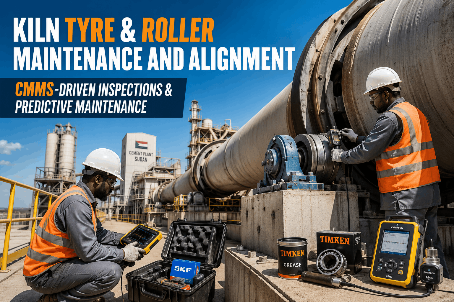
A rotary kiln carries hundreds of tonnes of shell, refractory and hot clinker on a small number of tyre and roller stations. When a roller axis drifts or a tyre starts to creep, the load concentrates on a narrow contact band and damage builds quietly for weeks. A disciplined round, recorded in Oxmaint maintenance management software, shows the drift early enough to plan the correction instead of reacting to a failure.
Rotary Kiln Tyre and Roller Alignment Inspection Checklist
A station-by-station inspection with condition indicators, maintenance actions and escalation criteria for kiln tyres, support rollers, thrust control and bearings.
Why Tyre and Roller Alignment Decides Kiln Availability
The kiln shell rests on riding rings, called tyres, which turn on pairs of support rollers. The kiln sits at a slope, so the whole assembly constantly tries to slide downhill, and the thrust roller and roller alignment manage that movement.
What drifts and how it shows
- Roller axes move out of parallel with the kiln axis, so the kiln walks up or down hill.
- Contact bands shift toward one edge of the tyre or roller face.
- Tyre creep grows as the gap between tyre and shell changes.
- Thrust roller load climbs and bearing temperatures rise on one side.
What it costs the plant
- Unplanned kiln stops that also upset the preheater and cooler.
- Shell ovality, cracking near tyre locations and refractory loss.
- Roller and tyre resurfacing that needs a long shutdown and heavy lifting.
- Repeated adjustments made without a baseline to measure against.
How to Use This Checklist
Each item lists the field check, the indicator that matters and the point at which to escalate. Frequency tags show who should run it and how often.
Tyre Condition and Creep
Support Roller Contact and Skew
Thrust Control and Axial Position
Roller Bearings and Lubrication
Shell, Foundations and Records
Condition Indicators and Maintenance Response
Keep Every Kiln Station Reading in One Record
Schedule station rounds, capture readings and photos on a mobile device, and trend creep and bearing temperature against baseline.
Common Root Causes of Alignment Problems
- Thermal growth that was not allowed for when rollers were last set.
- Foundation settlement or cracking that slowly moves roller bases.
- Worn chair blocks and filler bars that change the tyre to shell gap.
- Roller surface damage that alters contact and friction.
- Thrust system faults that leave the kiln stuck at one end of its travel.
- Uncontrolled adjustments with no record of what changed and why.
Recording Readings So They Can Be Trusted
Alignment decisions are only as good as the measurements behind them. Two technicians using different methods can produce readings that look like drift when nothing has moved.
- Use the same measurement point, tool and method at every round, and write the method into the inspection template.
- Record kiln load, feed rate and shell temperature with each reading so a change in operation is not mistaken for a change in condition.
- Photograph contact bands and tyre defects from the same position with a visible reference scale.
- Note whether the kiln was hot or cold and how long it had been at that condition.
- Flag any reading outside a believable range for a second check before it triggers work.
Planning the Correction During a Kiln Stop
Kiln stops are short and expensive, so alignment work has to be prepared well before the kiln cools. The checklist findings should already have defined the scope.
Operational Impact of Missing Early Warnings
When tyre and roller issues are found late, the response changes from planned correction to emergency repair, and the consequences spread beyond the kiln.
Production and quality
- Reduced feed or a stop to protect the shell and tyres.
- Clinker quality swings caused by unstable kiln operation.
- Extra stress on preheater, cooler and fans when the kiln restarts.
Maintenance and safety
- Emergency work in hot areas with limited planning time.
- Spare parts bought urgently or delayed by long lead times.
- More exposure for crews near heavy rotating equipment.
Trends and Technology for Kiln Support Stations
Many plants now combine manual rounds with condition monitoring so that the checklist focuses on trends instead of single readings.
Inspection Cycle From Round to Repair
Before and After a Structured Inspection Programme
Without a structured record
- Readings sit in notebooks and personal files.
- Drift is noticed after damage appears.
- Shutdown scope is estimated from memory.
- Adjustments repeat without learning.
With a structured record
- Readings are time-stamped by station.
- Trends trigger work orders earlier.
- Shutdown scope is built from evidence.
- Every adjustment has a reason and result.
Indicators That Show the Programme Works
| Indicator | What it shows | Review |
|---|---|---|
| Inspection completion rate | Whether station rounds are actually done | Weekly |
| Open watch and act findings | How much known risk is waiting for action | Weekly |
| Creep trend per station | Gap and chair block condition over time | Monthly |
| Bearing temperature spread | Load balance between rollers | Monthly |
| Unplanned kiln stops from mechanical causes | Impact of support station failures | Quarterly |
| Planned scope completed in the stop | Quality of shutdown planning | Per stop |
Where Oxmaint Fits the Kiln Maintenance Workflow
- Preventive maintenance schedules for rounds, lubrication and oil sampling.
- Asset records for each tyre, roller, bearing and thrust assembly with full history.
- Inspection templates with numeric fields, photos and escalation prompts.
- Work orders and spare parts tracking for planned kiln stop jobs.
- Dashboards that show overdue inspections, open defects and repeat findings.
- Condition-based workflows that raise work when a reading crosses a limit.
Escalation Rules Every Team Should Agree On
Clear rules stop findings from being discussed for weeks without a decision. Agree on them with operations, maintenance and reliability before the next round.
- Any confirmed crack in a tyre, roller or shell section goes straight to the reliability engineer and the plant manager.
- A bearing that stays warmer than its pair for several rounds gets an oil sample and a vibration check within the week.
- Creep that rises across consecutive readings gets a work order for chair block and gap inspection at the next stop.
- Persistent drift of the kiln toward one end triggers a review of roller settings and thrust behaviour.
- Any missed round is recorded as an exception with a named owner and a recovery date.
Frequently Asked Questions
How often should kiln tyres and rollers be inspected?
Follow the OEM plan, then shorten intervals when a trend appears. Book a demo to see how rounds are scheduled.
What does rising tyre creep indicate?
It often reflects a changing gap or worn chair parts. Trend it and escalate before it nears the limit.
Why compare contact lines hot and cold?
Thermal growth changes roller loading, so a cold check alone can hide misalignment.
Which readings should be recorded?
Creep, contact pattern, thrust position, bearing temperature, oil condition and photos of defects.
Can alignment history be kept digitally?
Yes. Oxmaint stores readings, photos and work orders against each kiln asset.
Move Kiln Alignment From Notebooks to Evidence
Give your team one place for station checks, defect trends and planned corrections before the next kiln stop.