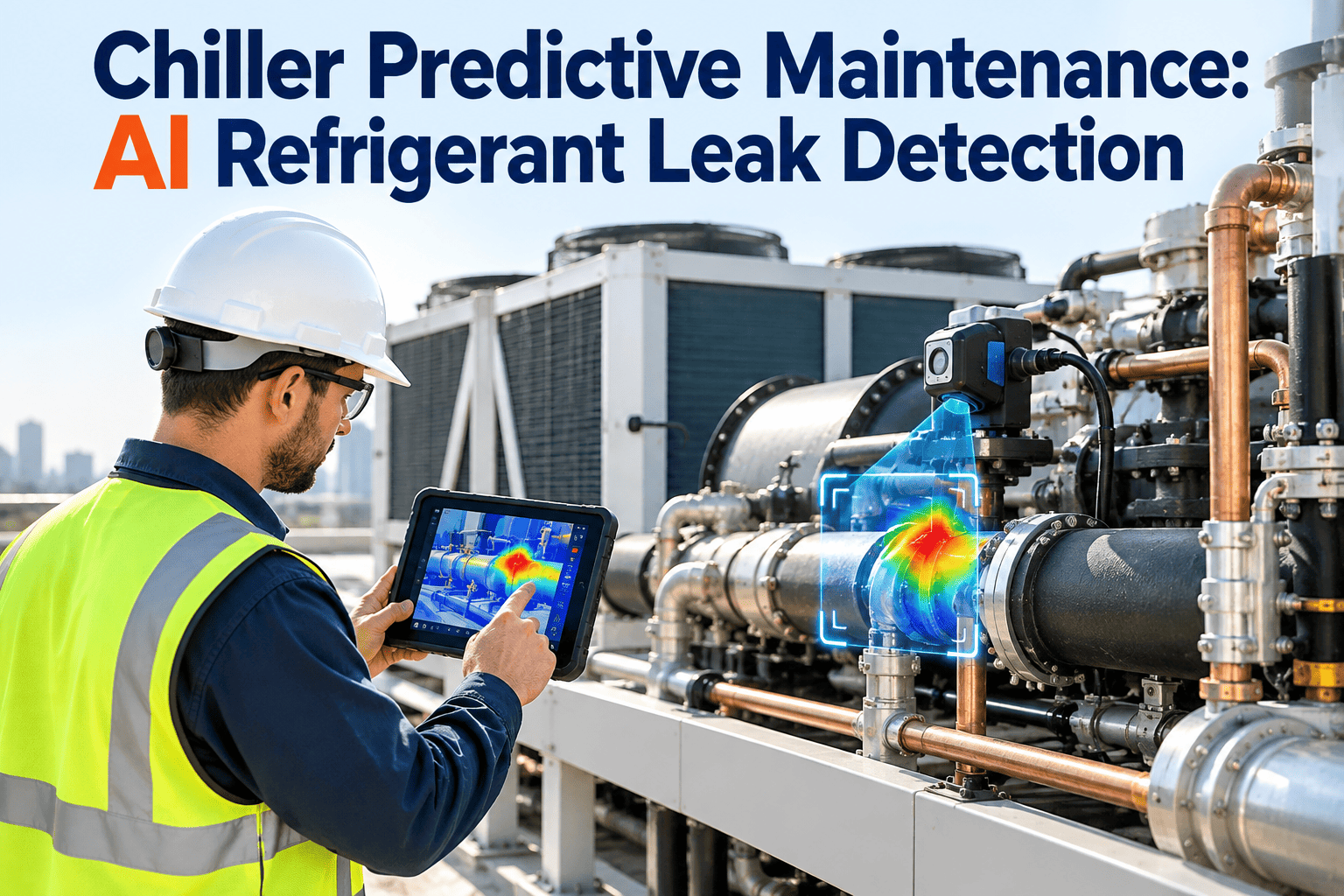
A chiller rarely announces a refrigerant leak. Charge drains slowly, efficiency slips a little each week, and the first loud signal is often a low-refrigerant trip on the hottest afternoon of the year. AI-assisted monitoring changes that timeline by learning what normal looks like for each machine and flagging the drift long before a safety cutoff. This guide explains the signals, the model logic, the 2026 compliance context, and how Oxmaint maintenance management software turns an alert into a verified, documented repair.
Chiller Predictive Maintenance: AI Refrigerant Leak Detection
Catch the slow drift that precedes a low-refrigerant trip. The sequence below shows where trend-based detection sits compared with the conventional protective alarm.
What a Slow Refrigerant Leak Actually Costs
The refrigerant itself is often the smallest part of the bill. The larger costs come from what a low charge does to performance, compliance, and the machine.
The 2026 Compliance Picture
Refrigerant rules changed significantly on January 1, 2026. The table summarizes the frameworks that most often touch commercial chillers.
| Framework | Who it covers | What it requires or recommends |
|---|---|---|
| EPA AIM Act HFC leak repair rule, effective January 1, 2026 | Appliances with 15 pounds or more of an HFC or substitute with a global warming potential above 53 | Leak rate calculation, repair when thresholds are exceeded (10 percent for comfort cooling, 20 percent for commercial refrigeration, 30 percent for industrial process), and records |
| EPA AIM Act automatic leak detection | Commercial refrigeration and industrial process systems with 1,500 pounds or more of covered refrigerant | Automatic detection on new systems from 2026 and on qualifying existing systems from 2027. It does not target typical comfort-cooling chillers. |
| EPA Section 608 | Ozone-depleting refrigerants, such as HCFC-123 used in low-pressure chillers | Technician certification, recovery, no venting, and leak repair obligations for larger charges |
| ASHRAE 147 | Owners and service providers of refrigerating and air-conditioning systems | Practices to reduce halogenated refrigerant release through design, leak detection, and service |
| ASHRAE 15 | Machinery rooms housing refrigeration equipment | Safety requirements including refrigerant monitoring and ventilation |
| CTI cooling tower standards | Water-cooled plants using cooling towers | Performance and testing practices for the tower that sets condenser water temperature |
Where the Signal Lives: Following the Refrigerant Cycle
A leak shows up in different places along the cycle. Sensors placed at each stage give a model enough context to tell a leak from other faults.
- Refrigerant pressure and saturation temperature
- Leaving chilled water temperature
- Evaporator approach
- Motor current and kilowatts
- Discharge temperature and superheat
- Oil pressure and oil temperature
- Condenser pressure
- Subcooling
- Entering and leaving condenser water
- Valve position or liquid level
- Purge run time on low-pressure units
- Machinery room refrigerant monitor
Why each signal matters for leak detection
| Signal | What it reveals | Leak relevance |
|---|---|---|
| Subcooling | How much liquid refrigerant leaves the condenser below saturation | Falls as charge is lost, one of the earliest indicators |
| Evaporator approach | Gap between leaving water temperature and refrigerant temperature | Widens as tube surface loses contact with liquid refrigerant |
| Kilowatts per ton | Electrical efficiency of the machine | Rises as capacity drops, though fouling can cause it too |
| Discharge superheat | Heat above saturation at the compressor outlet | Climbs when the compressor is starved of refrigerant |
| Purge run time | How often a low-pressure chiller removes non-condensables | Rises when leaks let air in on machines that run below atmospheric pressure |
| Room refrigerant monitor | Refrigerant concentration in the machinery room | Confirms a leak location and supports safety response |
How a Leak Behaves in Different Chiller Types
The same loss of charge produces different symptoms depending on machine design. Models should be configured per chiller type, not applied generically.
| Chiller type | How a leak shows up | Detection note |
|---|---|---|
| Water-cooled centrifugal, positive pressure | Charge drains outward, subcooling falls, approach widens | Trend subcooling and approach against load |
| Low-pressure centrifugal | Air and moisture can be drawn in, so purge activity increases | Track purge run time alongside condenser pressure |
| Screw chillers, air or water cooled | Refrigerant loss reduces capacity and raises superheat | Watch superheat, oil return, and slide valve behavior |
| Air-cooled scroll or modular units | Multiple independent circuits, each with a smaller charge | Monitor each circuit separately, since one may leak while others run well |
How the AI Model Separates a Leak From Everything Else
Telling faults apart: the discriminator table
| Pattern at steady load | Likely cause | What confirms it |
|---|---|---|
| Subcooling falls while evaporator approach widens, gradually over days | Refrigerant loss | Consistent drift, plus additions that restore performance temporarily |
| Condenser approach and head pressure rise, subcooling normal | Condenser tube fouling | Condenser water temperature difference and improvement after cleaning |
| High condenser pressure with rising purge activity | Air ingress on a low-pressure chiller | Purge counts and leak test of the low-pressure side |
| Rising discharge superheat with falling suction pressure | Low charge or a flow restriction | Pressure drop across filter drier and liquid line temperature |
| One sensor jumps while related signals stay steady | Sensor drift or fault | Cross-check against a redundant sensor or a calibrated reference |
What a useful alert shows the engineer
- The chiller, circuit, and refrigerant type, so the right leak rules apply.
- A trend chart of the affected signals at comparable load, not a single reading.
- The probable cause and a confidence level, with the alternatives the model ruled out.
- Recent refrigerant additions from the asset record, which help separate a leak from a sensor problem.
- A suggested inspection route, such as the joints and valves most likely to be involved.
Where Chiller Leaks Usually Start
Recording the location of every confirmed leak turns individual repairs into a fleet-wide pattern. These are the common starting points.
- Flanges, gaskets, and O-rings that harden with age and thermal cycling.
- Service valves, Schrader cores, and pressure transducer fittings that are disturbed during routine work.
- Shaft seals and connections on open-drive compressors.
- Relief devices and rupture discs, which can weep or release under abnormal pressure.
- Brazed joints that fatigue under vibration.
- Heat exchanger tubes, where a failure can move refrigerant into the water loop or draw water into the refrigerant circuit.
Lower-GWP refrigerants raise the stakes
Newer chiller refrigerants with lower global warming potential, some classed as mildly flammable, are entering the market. That makes early detection and sound machinery room safety practice more important, not less.
- Controller signals can be exported at a consistent interval.
- Key pressure and temperature sensors have a recent calibration record.
- Each chiller's refrigerant type and full charge are recorded on the asset.
- Past refrigerant additions are documented, even if only in paper logs.
Give Every Chiller Alert a Work Order and a Deadline
From Alert to Verified Repair: The Handoff Chain
Reactive Versus AI-Assisted: What Changes on the Plant Floor
- Leak found after a trip or during a scheduled check.
- Top-offs happen without a clear link to the leak location.
- Records live in notebooks, spreadsheets, or a technician's memory.
- Repeat leak points go unnoticed across chillers.
- Drift flagged while the machine still runs normally.
- Search is narrowed using the signals that moved.
- Every addition, test, and repair sits in the asset history.
- Fleet reports reveal repeat leak points and aging gaskets or joints.
Preventive Tasks That Support Leak Control
AI does not replace preventive maintenance. It sharpens it, and the scheduled tasks below give the model cleaner data. Follow your manufacturer's intervals.
| Frequency | Task | Purpose |
|---|---|---|
| Every shift or daily | Log operating pressures, temperatures, and amperage | Provides the trend record and validates sensor readings |
| Monthly | Inspect joints, valves, and fittings with an electronic detector | Finds small leaks at common leak points |
| Quarterly | Review purge operation and oil condition | Spots air ingress and contamination early |
| Annually | Inspect tubes, calibrate sensors, and test relief devices | Confirms heat exchanger integrity and instrument accuracy |
| After any repair | Leak test and post-repair trend review | Verifies the fix and supports compliance records |
KPIs That Show Whether the Program Works
Review these measures monthly for every chiller and quarterly for the fleet. Together they show whether alerts are turning into earlier, faster, and better-documented repairs.
A Deployment Roadmap With Clear Gates
Move forward only when each gate is met. Skipping the pilot is the most common reason AI monitoring loses the trust of the plant team.



.jpeg)

