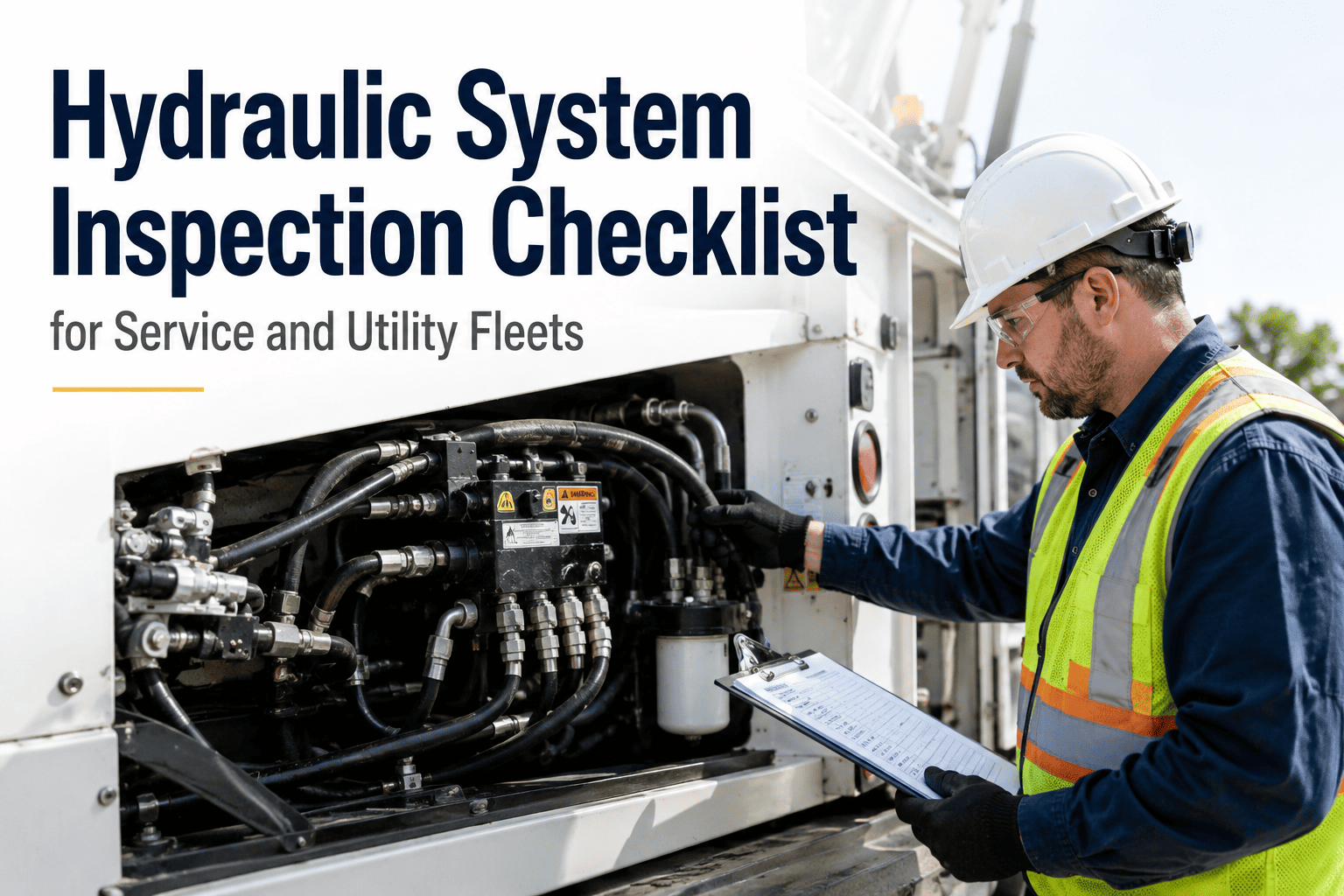
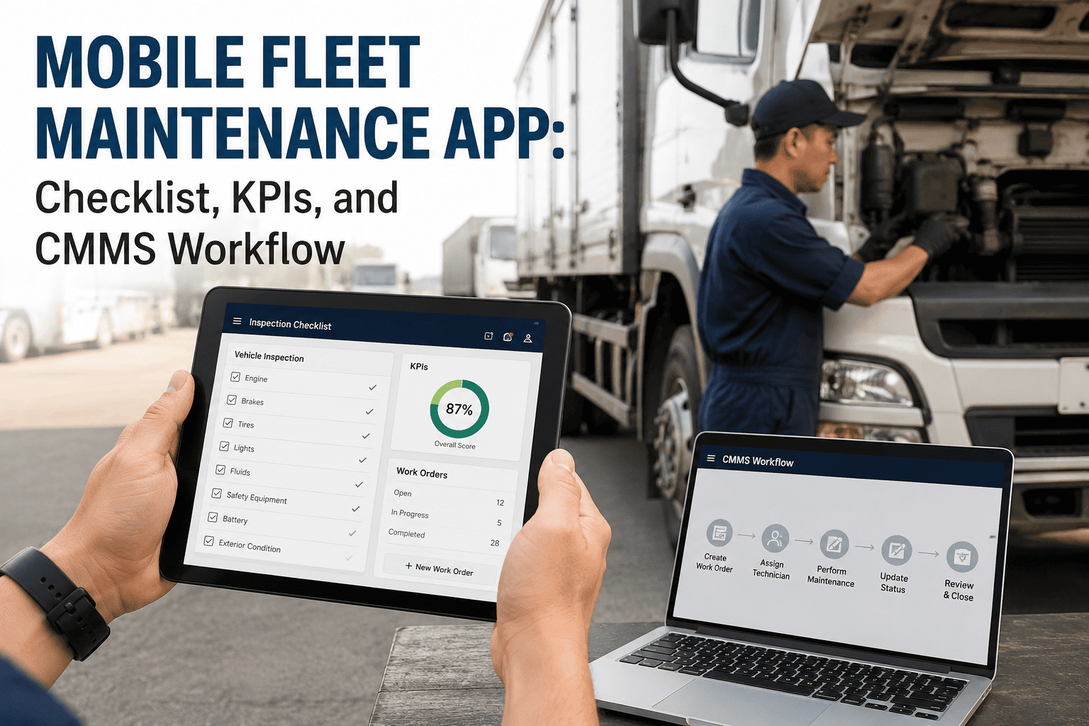
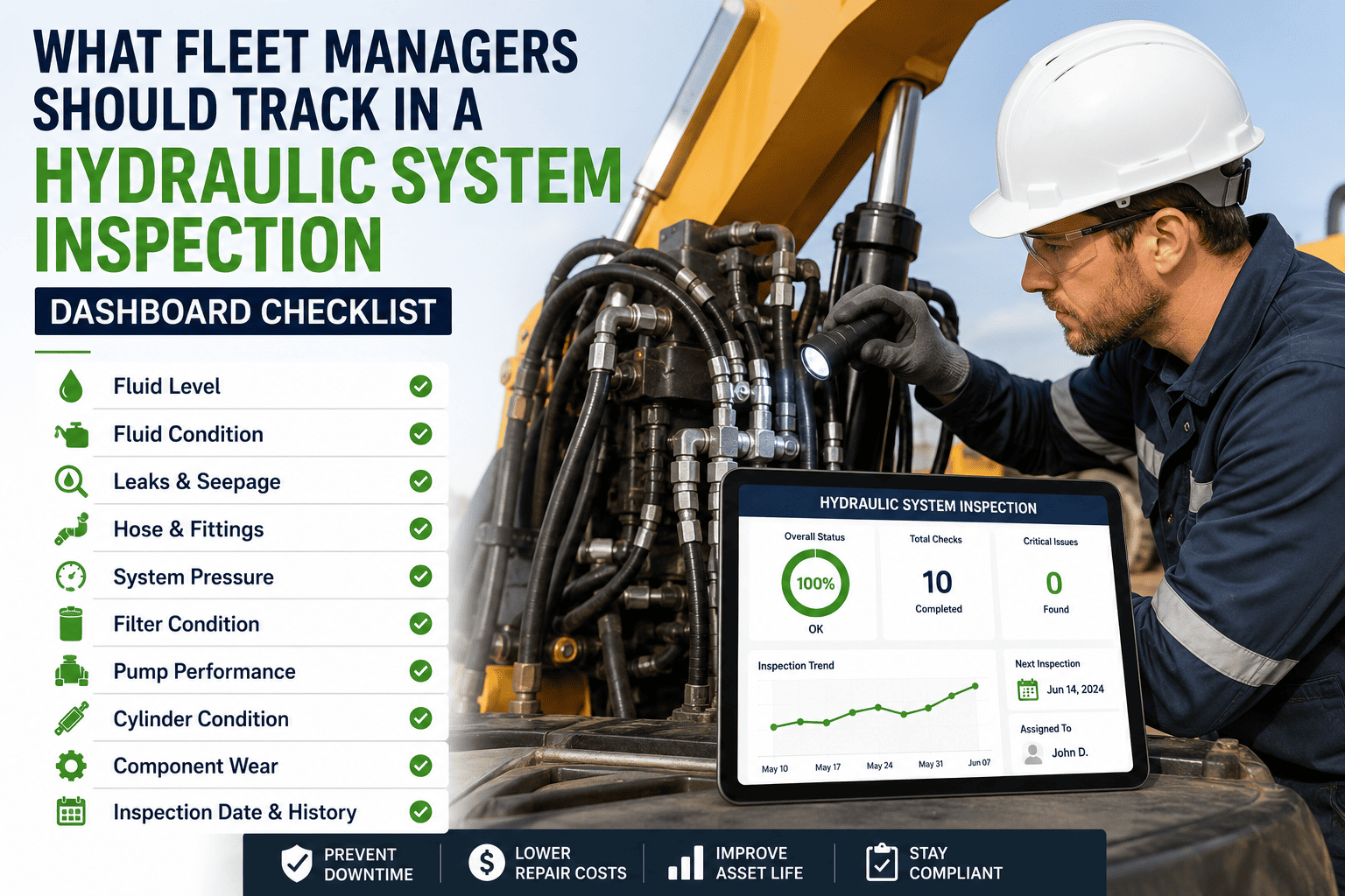
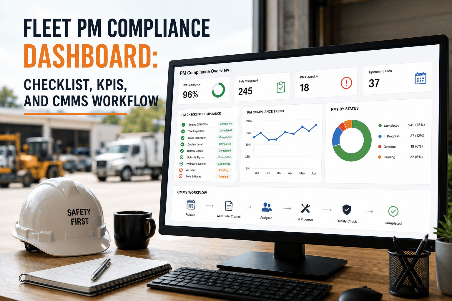
Service and utility fleets depend on hydraulic systems to perform core functions — from crane lifts and dump body raises to tailgate operation and aerial platform control. When hydraulic components fail in the field, vehicles are grounded, jobs are delayed, and emergency repair costs spike. A structured hydraulic system inspection checklist gives your maintenance team a repeatable framework to catch leaks, pressure drops, and fluid contamination before they become operational crises. This guide covers 40 critical inspection points across every hydraulic subsystem, paired with KPIs and CMMS integration steps for modern fleet operations. OxMaint helps service and utility fleet teams digitize every inspection, log findings, and schedule preventive maintenance from a single platform — Sign Up Free or to see it in action.
Stop Hydraulic Failures Before They Happen
OxMaint gives service and utility fleets digital inspection forms, real-time fault tracking, and automated PM scheduling — all connected to your hydraulic asset history.
73%
of hydraulic failures are caused by fluid contamination — all preventable with routine inspection
$8,400
average cost of an unplanned hydraulic pump replacement on a utility truck
3x
more expensive to fix hydraulic failures reactively vs. catching them during scheduled inspection
Section 1: Hydraulic Fluid System
Fluid condition is the primary indicator of overall hydraulic system health. Contaminated or degraded fluid accelerates wear across every downstream component — pumps, valves, cylinders, and actuators all suffer when fluid quality is ignored.
1. Fluid Level Verification
Inspect reservoir fluid level with the system cold and at rest. Low fluid levels indicate either leakage or evaporation loss — both require immediate investigation before the vehicle is returned to service duties.
2. Fluid Color and Clarity Check
Healthy hydraulic fluid is clear to amber. Milky or foamy fluid indicates water contamination; dark brown or black fluid signals thermal degradation. Either condition requires immediate fluid replacement and root cause investigation.
3. Fluid Particle Contamination Test
Use a particle count test or fluid analysis kit to verify ISO cleanliness levels. Metal particle presence in hydraulic fluid indicates internal component wear — pump gear wear, cylinder scoring, or valve body erosion that will worsen without intervention.
4. Reservoir Breather Filter Condition
Inspect breather filter for clogging and contamination. A blocked breather creates negative pressure in the reservoir, causing cavitation at the pump inlet — one of the most destructive conditions for hydraulic pump longevity in mobile applications.
5. Return Line Filter Inspection
Check return filter differential pressure indicator and filter element condition. Bypassed or clogged return filters allow contaminants to circulate through the entire system — accelerating wear on every precision-clearance component in the hydraulic circuit.
6. Fluid Temperature at Operating Load
Monitor hydraulic fluid temperature under normal operating load using an infrared thermometer or inline sensor. Operating above 80°C accelerates fluid oxidation, degrades seals, and reduces system efficiency — a critical threshold for any utility fleet running continuous hydraulic cycles.
Section 2: Hydraulic Pump Inspection
The hydraulic pump converts mechanical power into flow — and is the highest-cost component in most mobile hydraulic systems. Early wear detection at inspection prevents catastrophic pump seizure events that ground vehicles for days.
7. Pump Output Pressure Test
Connect a pressure gauge at the pump outlet and verify output pressure matches OEM specification under no-load and full-load conditions. Pressure drop of more than 10% below spec indicates internal wear — volumetric efficiency loss that reduces actuator speed and lifting capacity.
8. Pump Noise and Vibration Assessment
Listen for abnormal cavitation or aeration noise at the pump during operation. Whining, knocking, or rattling sounds indicate inlet starvation, bearing wear, or internal component damage — each requiring further diagnosis before additional operation is permitted.
9. Pump Case Drain Flow Check
Measure case drain flow rate on piston pumps to assess internal leakage. Excessive case drain flow indicates worn barrel and piston assemblies — a reliable predictor of imminent pump failure that allows planned replacement rather than emergency roadside breakdown.
10. Pump Shaft Seal Leak Inspection
Inspect pump shaft seal area for fluid seepage. Shaft seal failures allow contamination ingress and cause fluid loss. Early seal replacement costs under $150; a contamination-induced pump failure costs $2,000 to $6,000 depending on pump type and vehicle class.
Section 3: Hoses, Lines and Fittings
Hydraulic hose failures are the most frequent cause of fluid releases and environmental incidents in fleet operations. A thorough visual inspection of every hose, line, and fitting saves both equipment and compliance exposure.
11. Hose Outer Cover Condition Check
Inspect all hydraulic hoses for abrasion, cracking, blistering, and kinks along full length. Outer cover damage exposes reinforcement layers to moisture and mechanical wear — compromising burst pressure rating and creating a blowout risk under peak operating conditions.
12. Fitting and Crimp Integrity Inspection
Inspect all hose end fittings and crimps for corrosion, cracking, and seeping fluid. Damaged crimps fail progressively — a small weep under pressure testing becomes a full hose separation at operating pressure, often during peak load cycles in the field.
13. Rigid Line Corrosion and Routing Check
Inspect steel hydraulic lines for external corrosion, dents, and improper routing that causes chafing against frame components. Corroded or chafed lines on service trucks in northern climate operations are a leading source of fluid releases and unexpected downtime.
14. Quick Coupler Seal and Function Test
Test all quick-disconnect couplers for positive engagement, seal integrity, and dirt exclusion cap condition. Damaged quick coupler seals allow system contamination every time attachments are changed — a significant contamination pathway in multi-attachment utility fleet operations.
Section 4: Cylinders and Actuators
15. Cylinder Rod Seal External Leak Test
Inspect cylinder rod surfaces for scoring and inspect seal areas for external leakage. A leaking rod seal causes both fluid loss and rod scoring — once a rod is scored, the seal replacement alone will not resolve the leak and full cylinder rebuild becomes necessary.
16. Cylinder Drift Test Under Load
With load applied to the cylinder, monitor position drift over a 5-minute period. Excessive drift indicates internal seal bypass — a safety-critical condition in lifting applications where load holding is required for worker safety under elevated platforms or suspended loads.
17. Rod Chrome Condition Assessment
Inspect cylinder rods for pitting, rust, and chrome delamination. Damaged rod surfaces destroy seals on each extension cycle — creating a recurring maintenance cost that only resolves with rod re-chroming or cylinder replacement. Early detection prevents progressive damage escalation.
18. Cylinder Mount Pin and Bushing Wear
Check cylinder clevis and trunnion mount pins for wear and bushing condition. Worn pivot bushings create misalignment loads on cylinder rods — bending forces that accelerate side-load seal wear and reduce cylinder service life significantly in heavy-cycle service truck applications.
Section 5: Valves and Control Systems
19. Relief Valve Setting Verification
Test main system relief valve setting under loaded conditions using a calibrated pressure gauge. An incorrectly set or stuck relief valve either limits system performance or allows dangerous over-pressure conditions — both create operational and safety issues in utility fleet work cycles.
20. Directional Control Valve Function Test
Operate all directional control valve positions through full stroke and verify smooth actuation without sticking or hesitation. Contamination-induced spool sticking in directional valves causes erratic actuator response — a significant safety concern in aerial work platform and crane applications.
21. Load-Holding Valve Integrity Check
Test counterbalance and load-holding valves by cycling loads and monitoring for unintended movement. Failed load-holding valves create immediate drop risk in lifting applications — one of the most severe safety failures possible in utility fleet hydraulic systems.
22. Electro-Hydraulic Solenoid Response Test
Energize each solenoid valve and verify correct actuation response. Inspect solenoid connectors for corrosion and wire chafing. Corroded solenoid connections are a leading cause of intermittent hydraulic function loss in utility vehicles operating in outdoor weather-exposed environments.
Section 6: PTO and Power Source
23. PTO Engagement and Disengagement Test
Test power take-off engagement smoothness and full disengagement under operating conditions. PTO engagement problems indicate worn clutch packs or shift mechanism issues — failures that cause hydraulic system unavailability during critical field operations.
24. PTO Output Shaft and Coupling Condition
Inspect PTO output shaft for wear and verify pump coupling alignment and torque. Misaligned pump couplings create bending loads on pump shafts — leading to premature shaft seal failure and pump bearing wear that shortens service life and increases unscheduled maintenance frequency.
25. Auxiliary Engine or Electric Drive Assessment
For vehicles with dedicated auxiliary engines or electric hydraulic drives, inspect the drive unit independently. Verify fuel or electrical supply integrity, cooling system condition, and mounting security — failures in auxiliary drives can ground the entire hydraulic capability of specialized service trucks.
Section 7: Safety and Compliance Systems
Hydraulic system safety interlocks and overload protection devices are regulatory requirements in most jurisdictions for aerial, crane, and tipper truck operations. Inspecting these systems is not optional — it is a liability management requirement.
26. Overload and Pressure Switch Function
Test hydraulic pressure switches and overload protection cutoffs by simulating over-pressure conditions in a controlled environment. Non-functional overload protection exposes vehicles to catastrophic structural failure under tipping or overloading conditions in utility operations.
27. Emergency Lowering System Test
Operate manual emergency lowering controls for aerial platforms and crane systems to verify function independent of primary hydraulic power. Emergency lowering capability is a mandatory safety requirement — its failure puts workers at elevated height risk in any power loss scenario.
28. Hydraulic Interlocks and Travel Locks
Verify that travel interlock systems prevent vehicle movement with boom or outriggers deployed. Confirm outrigger interlocks disengage driving circuits when stabilizers are extended. These safety interlocks prevent the most serious hydraulic-related accidents in utility fleet operations.
29. Outrigger and Stabilizer System Check
Inspect outrigger cylinders for external leaks, pad condition, and full extension capability. Test float pad foot rotation and load distribution. Compromised outriggers reduce effective lifting radius and create machine tipping risk — unacceptable in roadside utility work operations.
Section 8: Attachments and Work Equipment
30. Boom and Arm Hydraulic Circuit Integrity
Cycle boom, arm, and bucket circuits through full range while monitoring for jerky motion, speed variation, and drift. Uneven circuit performance indicates worn spools, incorrect relief settings, or contamination-induced flow restriction affecting work productivity and operator safety.
31. Hydraulic Tool Circuit Pressure Test
Verify auxiliary tool circuit pressure and flow at the work tool coupler matches attachment OEM specifications. Under-pressure circuits reduce tool performance and productivity; over-pressure conditions risk tool hydraulic motor damage — both are common in multi-tool utility fleet environments.
32. Liftgate Hydraulic System Inspection
Test liftgate through full raise, lower, and tilt cycles under rated load. Inspect hydraulic cylinder, pump unit, and hose condition. Liftgate failures during delivery operations create both safety incidents and service level agreement violations that impact customer relationships.
33. Tipper Body Raise and Lower Circuit Check
Raise the tipper body to full elevation and hold for 3 minutes while monitoring for drift. Inspect underbody cylinder for seal leaks and pivot pin condition. An unintentional tipper drop under a worker performing underbody maintenance is a life-safety critical failure scenario.
Section 9: Cooling and Heat Management
34. Hydraulic Oil Cooler Inspection
Inspect oil cooler core for blockage and fin condition. Clean or damaged cooler cores cannot maintain safe operating temperatures under sustained duty cycles — thermal runaway in high-ambient-temperature summer operations accelerates fluid degradation and seal failure across all circuits.
35. Thermostatically Controlled Cooling Circuit Test
Verify hydraulic thermostat valve opens and routes flow to the cooler at the correct temperature setpoint. A stuck-closed thermostat bypasses the cooler entirely — causing rapid temperature rise to dangerous levels without visible warning during field operations.
Section 10: Documentation and CMMS Integration
36. Inspection Finding Documentation and Severity Rating
Record all inspection findings with severity ratings — critical, major, or minor — and assign corrective work orders immediately. OxMaint's inspection module captures findings with photo evidence and generates work orders automatically, eliminating manual handoff delays between inspection and repair.
37. Fluid Sample Documentation and Lab Submission
Log fluid sample collection date, sample ID, and lab submission tracking in your CMMS. OxMaint tracks fluid analysis history per asset — enabling trend analysis that identifies when fluid condition is degrading faster than expected and triggering early intervention before component damage occurs.
38. Component Replacement History Update
Update CMMS with all component replacements performed during or following inspection. Accurate component age records in OxMaint enable predictive replacement scheduling — preventing the scenario where a recently replaced pump seal fails prematurely because installation date was never recorded.
39. Regulatory Compliance Inspection Logging
Record all safety system function tests and compliance inspection outcomes in your CMMS for audit trail purposes. Many jurisdictions require documented proof of periodic hydraulic safety system testing for aerial platforms and cranes — OxMaint creates this audit trail automatically from each inspection.
40. PM Schedule Update Based on Findings
Adjust preventive maintenance intervals based on inspection findings and operating condition history. OxMaint automatically recommends PM interval adjustments when inspection data indicates a vehicle is operating in conditions that accelerate hydraulic component wear beyond standard service schedules.
Hydraulic System Inspection KPIs for Fleet Managers
| KPI Metric |
Target Benchmark |
Action Threshold |
| Hydraulic system inspection completion rate |
100% of scheduled inspections |
Review if below 95% |
| Fluid cleanliness ISO rating |
ISO 16/14/11 or better |
Flush if exceeds ISO 18/16/13 |
| Hose failure incidents per 100 vehicles/year |
Less than 2 |
Audit hose replacement program if above 4 |
| Hydraulic-related downtime as % of total downtime |
Less than 15% |
Increase inspection frequency if above 20% |
| Mean time between hydraulic failures |
Greater than 1,800 operating hours |
Root cause analysis if below 1,200 hours |
| Open hydraulic safety defect work orders |
Zero open critical items |
Immediate escalation for any safety-critical finding |
Track Every Hydraulic KPI Across Your Entire Fleet
OxMaint centralizes inspection data, maintenance history, and KPI dashboards for every vehicle in your service and utility fleet — giving managers real-time visibility into hydraulic system health across all locations.
Frequently Asked Questions
How often should a hydraulic system inspection be performed on service vehicles?
Most service and utility fleets perform a full hydraulic inspection every 250 operating hours or 3 months, whichever comes first. Vehicles in high-duty or contaminated environments should increase frequency to every 150 hours.
OxMaint automates interval tracking so no inspection is ever missed.
What is the most common cause of hydraulic hose failure on utility trucks?
Abrasion against frame components and heat degradation near exhaust routing are the two leading causes. Inspecting hose routing and adding protective sleeving at wear points significantly extends hose service life.
Book a Demo to see how OxMaint tracks hose replacement history by vehicle.
Can OxMaint be used to schedule hydraulic system inspections across multiple locations?
Yes. OxMaint supports multi-site fleet operations with centralized scheduling, location-based asset filtering, and inspection completion dashboards visible to fleet managers across all locations from a single login — making it ideal for utility companies operating regional service fleets.
What documentation is required for hydraulic safety system compliance?
Most jurisdictions require dated inspection records showing safety system function test results for aerial platforms and crane vehicles. OxMaint creates a timestamped, technician-signed digital audit trail for every inspection — meeting regulatory documentation requirements automatically without paper records.
How does hydraulic fluid analysis reduce maintenance costs?
Fluid analysis identifies contamination and wear metals before visible symptoms appear, enabling targeted intervention that costs far less than replacing worn components reactively. Fleets using regular fluid sampling with
OxMaint tracking typically reduce hydraulic repair costs by 20 to 35% within the first year.