A hydraulic system inspection without a connected CMMS workflow is a record-keeping exercise, not a maintenance program. The inspection finds the symptom; the KPI confirms the trend; the CMMS work order triggers the repair — and only when all three are linked does inspection activity translate into reduced downtime. Fleet maintenance teams that connect hydraulic inspection findings directly to CMMS work orders report a 60% reduction in time-to-repair on hydraulic defects. Whether your fleet runs excavators, mobile cranes, or industrial presses, the combination of a structured checklist, measurable KPIs, and a CMMS-integrated workflow is what separates a hydraulic program that works in the field from one that only works on paper. Sign Up Free to connect your hydraulic inspections to Oxmaint's CMMS workflow, or to see how defect-to-work-order conversion happens in under 60 seconds.
Connect Hydraulic Inspections to CMMS Work Orders Automatically
Oxmaint captures hydraulic inspection findings on mobile, converts defects to work orders without manual entry, and tracks KPIs per asset — giving maintenance managers a live picture of hydraulic fleet health across every site and shift.
Section 1: Fluid Condition and Contamination Checklist
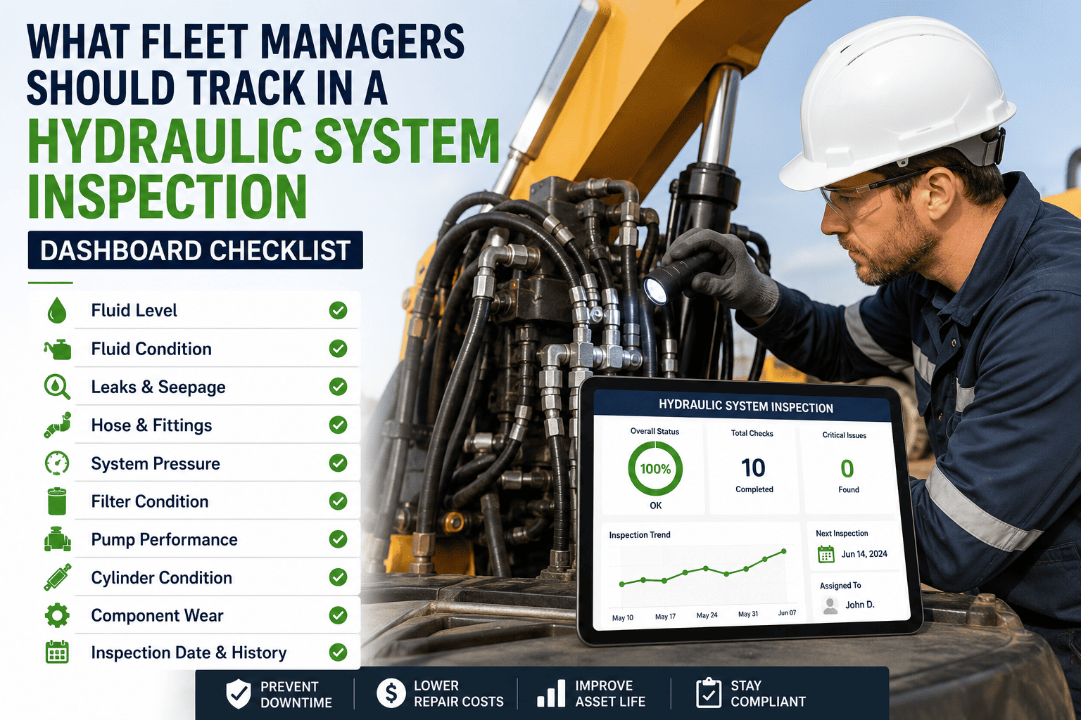
Fluid condition items must be completed first — all other inspection zones are secondary to confirming the hydraulic fluid is clean, at the correct level, and free from water contamination. A failing result here stops the inspection and triggers an immediate work order.
Reservoir fluid level — within min/max marks on sight glass at ambient temperature
Check level before startup — thermal expansion at operating temperature makes level readings unreliable. Any level below the minimum mark is an immediate out-of-service condition; operating below minimum draws air into the suction line and begins pump cavitation within minutes. OOS — level below minimum mark
Fluid colour and clarity — clear amber, no milky discolouration, no visible particles
Milky fluid indicates water ingress through a failed breather or heat exchanger. Particulate visible to the naked eye indicates catastrophic contamination — the ISO 4406 cleanliness level is likely above 21/19/16. Neither condition permits continued operation without sampling and root cause identification. OOS — milky, dark, or visibly contaminated fluid
Breather cap condition — clean, seated correctly, restriction indicator in green zone if fitted
A clogged breather creates negative pressure in the reservoir that draws contaminated air past the cap seal. The breather is the highest-frequency replacement item in a hydraulic contamination control program — service interval should not exceed 250 operating hours in dusty environments. Defect — clogged or displaced breather cap
Return line filter indicator — green zone, no bypass lamp or warning active
A filter in bypass is the single most damaging operating condition in a hydraulic system — it passes contamination from every upstream component directly to the pump suction. Any bypass indication triggers an immediate OOS and filter replacement before the equipment is restarted. OOS — bypass lamp active or indicator in red zone
Reservoir exterior — no external leaks, no seepage from drain plug or access covers
Reservoir seepage that is ignored during inspection becomes a slow fluid loss event that drops the system below minimum level mid-operation. Log location of any seepage with a photo — even minor weeping must be traced to a fitting or seal before the next inspection. Defect — any seepage from reservoir body, plugs, or covers
Section 2: Pump, Motor, and Drive System Checklist
Pump condition determines the performance ceiling of the entire hydraulic circuit. These items detect pump wear, drive problems, and pressure delivery issues before they produce complete circuit failure.
Pump startup noise — quiet operation, no cavitation knock, whine, or intermittent surging
Cavitation produces a characteristic rattling or knocking from the pump body. Whining indicates inadequate fluid viscosity or low suction pressure. Both are early-stage damage indicators — the pump is still functioning, but internal erosion has begun. Continued operation accelerates wear exponentially. OOS — any cavitation noise or abnormal pump sound at startup
System pressure at rated load — within OEM specification, no pressure fluctuation under steady load
Measure system pressure with a calibrated gauge at rated load — do not rely on the cab-mounted gauge, which typically has ±10% accuracy. Pressure below OEM specification at rated load indicates internal pump bypass or a failing pressure relief valve. Document the reading for trend analysis against previous inspections. OOS — pressure below OEM specification at rated load
Case drain flow — within OEM specification, no excessive flow indicating internal bypass
Case drain flow above OEM specification confirms the pump is bypassing internally — volumetric efficiency is falling. Record the flow reading at each inspection against the baseline taken at installation. A trend of increasing case drain flow over successive inspections is the most reliable early warning of pump end-of-life before output pressure is visibly affected. Defect — case drain flow above OEM specification
Drive coupling — no rubber insert deterioration, correct alignment, no play in coupling hub
A deteriorated rubber coupling transmits shock loads and vibration to the pump inlet shaft, accelerating bearing wear and seal failure. Inspect with the machine shut down — squeeze the rubber insert and check for cracking. Any cracking requires immediate replacement; coupling failure under load produces immediate pump damage. Defect — any cracking, play, or deterioration in coupling insert
Section 3: Cylinders and Actuators Checklist
Cylinder condition affects both load-holding safety and hydraulic circuit efficiency. These items identify seal failures and rod surface damage before they create a safety event or circuit bypass that reduces overall system pressure.
Rod seal condition — no external leakage at any cylinder rod, no oil film on rod surface
A wet rod seal is leaking. A dry rod with no film is not. The inspection standard is a dry rod surface — an oil film that builds between inspection cycles indicates a seal that is passing fluid under pressure. Any external cylinder leakage on mobile plant is an immediate OOS — fluid on exhaust components creates a fire risk. OOS — any external leakage at cylinder rod seal
Rod surface — no scoring, chrome delamination, pitting, or impact damage on rod surface
A scored rod destroys replacement seals on first stroke — abrasive particles from the scoring site are drawn behind the wiper on every extension cycle. Always inspect the rod surface before authorising a reseal. A scored rod requires assessment for grinding, chrome repair, or replacement before any new seal installation. OOS — any scoring or chrome damage on rod surface
Cylinder drift — no unloaded drift beyond OEM specification at full extension under rated load hold
Internal bypass through worn piston seals produces drift without external leakage. Test at full extension under rated load — hold for 60 seconds and measure any retraction. Drift within 0–3mm is typical for most cylinders; beyond OEM specification confirms piston seal bypass requiring internal reseal. Defect — drift beyond OEM specification under 60-second load hold
Cylinder mounting and pivot pins — no excessive lateral play, grease nipples present and serviceable
Worn pivot pin bushings introduce side loading on the cylinder rod, accelerating rod seal and wiper wear. Check lateral play by attempting to move the rod laterally with the cylinder at mid-stroke — any movement beyond 1–2mm requires bushing inspection and measurement. Defect — lateral play beyond 2mm or missing grease nipples
Section 4: Hoses, Fittings, and Valve Block Checklist
Hose and fitting integrity is both a safety and a contamination control issue. A ruptured high-pressure hose is a 250-bar fluid injection hazard. A weeping fitting introduces atmospheric contamination on pressure drop cycles.
High-pressure hoses — full-length inspection, no blistering, abrasion, kinking, or end fitting damage
Walk the full hose run and inspect every inch — blistering appears where inner reinforcement has failed, not necessarily where the hose is most visible. Any blister, regardless of size, is a structural failure and an immediate OOS. Abrasion through the outer cover to the first reinforcement layer is also an OOS condition. OOS — any blistering, kinking, or reinforcement exposure
Fittings and port connections — dry at all connection points, no seepage tracks or residue
Use a clean white cloth to wipe each fitting connection — any colour transfer indicates active seepage. Document the fitting location and classification (JIC, ORFS, NPT) in the inspection record. Repeat seepage after re-torque confirms a damaged seat or wrong thread specification — re-torque is not an adequate corrective action for repeat-seeping fittings. Defect — any seepage trace at any fitting or port
Valve block and manifold — no external leakage at valve body, solenoids correctly seated
Leakage from a valve block body (not at fittings) indicates an internal seal failure or a crack in the manifold casting. This type of leak will not be resolved by re-torquing fittings — a valve block internal reseal or replacement is required. Document the leak location with a photo before cleaning, to allow accurate diagnosis. Defect — any leakage from valve block body or manifold casting
Hose routing — no contact with heat sources, sharp edges, or moving components along full hose run
Hose contact with a turbocharger housing, exhaust manifold, or rotating shaft does not produce an immediate leak — it produces an accelerating deterioration of the outer cover and inner liner over 200–400 operating hours that ends in a failure event. Flag any contact during inspection and route before the next operating period. Advisory — reroute before next operating period
Section 5: Heat Exchanger and Thermal Management Checklist
Thermal management failures produce seal failures and fluid degradation across the entire hydraulic circuit. A blocked heat exchanger does not cause a single visible defect — it causes cumulative damage to every elastomeric seal in the system.
Heat exchanger core — clean, no debris blockage on fins, airflow not restricted
A blocked heat exchanger core reduces cooling capacity by up to 70% without producing any alarm or warning light in most mobile plant. Clean with compressed air (not water) whenever debris is visible. In construction or agricultural environments, clean at every shift change during dry weather operations. Defect — visible debris blockage on exchanger fins
Cooling fan — operational, correct rotation direction confirmed, no blade damage
A hydraulically-driven cooling fan that is running in reverse direction (incorrect rotation) provides near-zero cooling capacity but does not trigger a high-temperature warning until the fluid has already exceeded safe operating limits. Confirm rotation direction against the OEM specification at every scheduled inspection. OOS — fan not operational or running in incorrect direction
Fluid temperature at operating load — within OEM maximum, no sustained exceedance
Log fluid temperature at peak operating load against the OEM maximum. A temperature that was within specification last inspection but is now within 5°C of the maximum indicates a deteriorating thermal management system — blocked exchanger, fan slip, or thermostat bypass valve sticking partially closed. Trend the reading to detect deterioration before the maximum is reached. Advisory — log temperature every inspection for trend analysis
Hydraulic Inspection KPIs and What They Signal
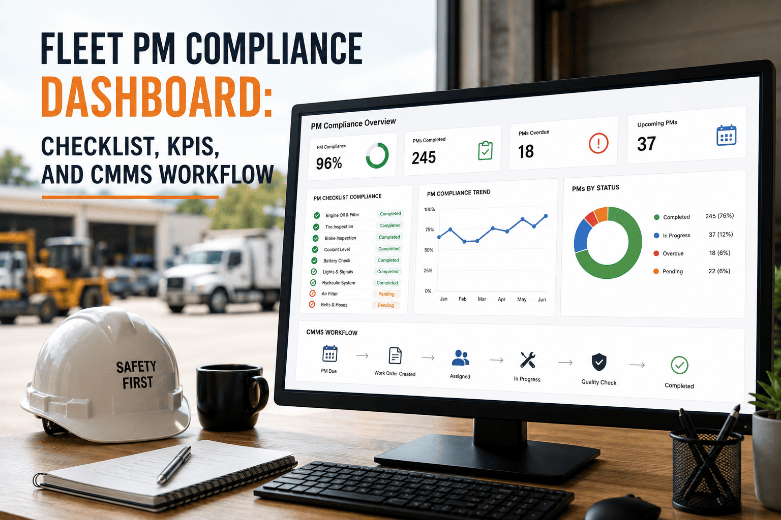
KPIs convert inspection records into management decisions. The following six metrics map directly to CMMS data fields that Oxmaint captures automatically from completed hydraulic inspection records.
| KPI | What It Measures | Benchmark Target | Warning Signal |
|---|---|---|---|
| MTBF | Mean time between hydraulic failures per asset class | 20% increase within 6 months of program launch | Flat MTBF after 3 months — checklist items not detecting defects |
| Completion Rate | Scheduled inspections completed on time, per asset | 95% or above within 60 days of program launch | Below 85% — checklist too long or tool not being used in field |
| Defect Detection Rate | Failures pre-empted by inspection vs total failures | Above 80% of hydraulic failures detected before breakdown | Below 60% — inspections are missing pre-failure indicators |
| WO Conversion Time | Defect recorded to work order assigned in CMMS | Under 60 minutes for any defect severity | Above 4 hours — manual work order creation causing delays |
| Repeat Defect Rate | Same component defects recurring within 90 days | Below 10% of work orders are repeat defects | Above 20% — repairs not addressing root cause |
| Planned Ratio | Planned work orders as proportion of all hydraulic WOs | Above 70% planned within 12 months of program launch | Below 50% — program not pre-empting failures effectively |
Frequently Asked Questions
Common questions from maintenance engineers and fleet managers about hydraulic inspection KPIs, CMMS integration, and building workflows that reduce downtime rather than just producing records.
Run Hydraulic Inspections That Connect Directly to Your CMMS
Oxmaint links every hydraulic inspection finding to a CMMS work order automatically — giving your maintenance team the KPI visibility and defect-to-repair workflow that reduces hydraulic downtime across every asset in the fleet.