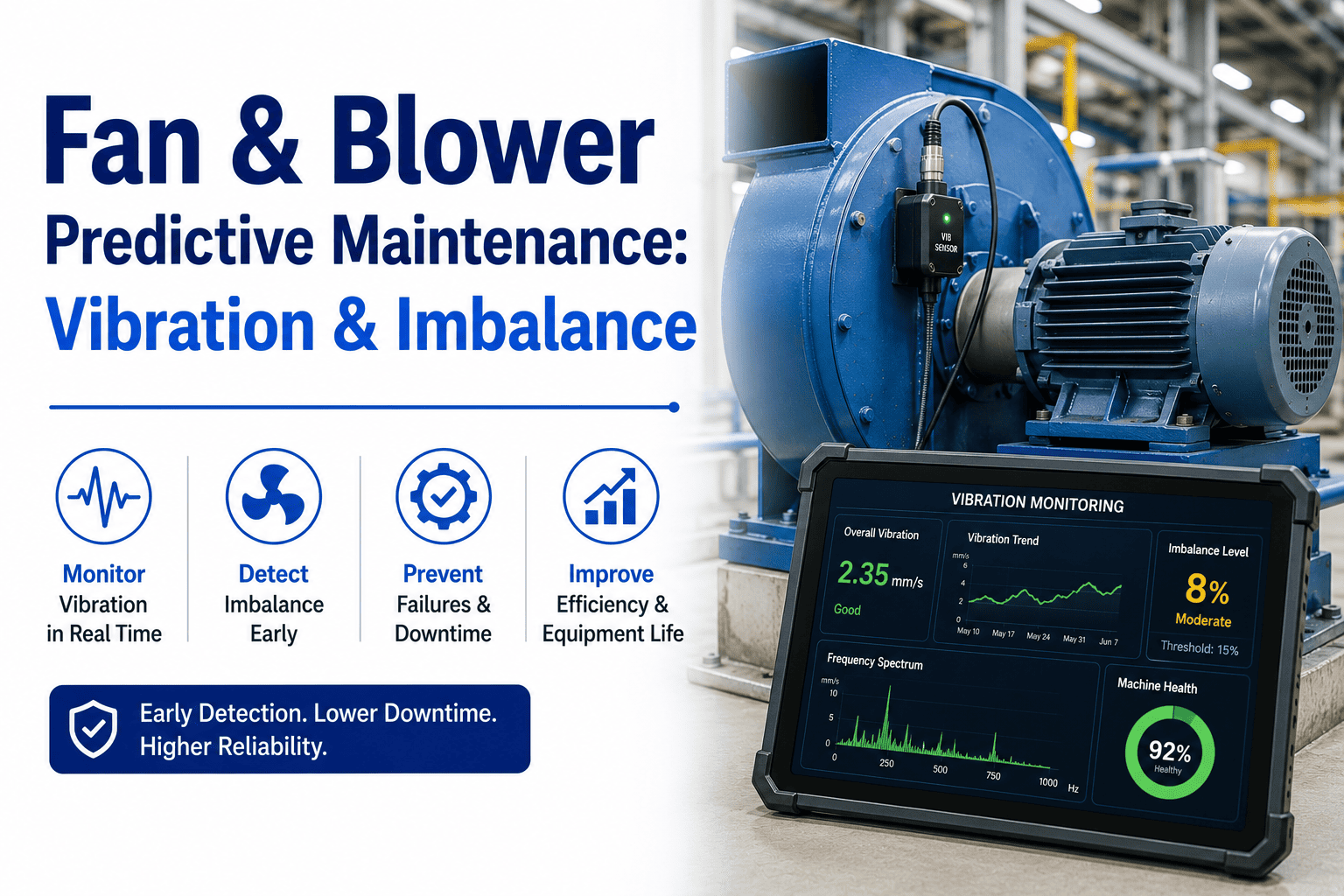
Industrial fans and blowers are the quiet workhorses of manufacturing — running 24/7 in dust collectors, boiler combustion air systems, kiln exhaust, drying lines and process ventilation, yet they rarely get attention until a failure shuts the line. Over 60% of unplanned fan outages trace back to just three failure modes: rotor imbalance, bearing degradation and aerodynamic instability, all of which announce themselves in the vibration spectrum days or weeks before they become critical. This guide walks through the predictive maintenance playbook for fans and blowers — the imbalance signatures to watch, the bearing fault frequencies that matter, the aerodynamic warning signs, and how to operationalize a route inside your CMMS with defensible alarm thresholds. Ready to stop reacting to fan failures? Start Free Trial and build your first monitored asset route in under an hour.
What if your fans told you they were failing — 30 days before they did?
Vibration signature analysis catches rotor imbalance, bearing defect frequencies and aerodynamic stall in the early stage — turning a $14,000 emergency outage into a $900 planned bearing swap. Build a defensible PdM route for every fan in your plant.
Three failure modes cause most unplanned fan outages
Across heavy-process plants, three mechanical signatures account for the overwhelming majority of fan and blower failures. Knowing which one you are chasing determines the sensor, the analysis window and the corrective action.
Rotor Imbalance
Material buildup, eroded impeller blades or a shed balance weight produce a clean 1× running-speed peak. Left unchecked, a 25 g·mm imbalance on a 50 kg rotor can push bearing life below 6 months.
Bearing Wear
Inner-race, outer-race, cage and rolling-element defect frequencies are calculable from bearing geometry. A rising envelope-acceleration trend at BPFO is the single most reliable 30-day lead indicator.
Aerodynamic Instability
Stall, surge and inlet-outlet vortex shedding show up as sub-synchronous (≈0.7×) and broadband turbulence. Often triggered by damper repositioning or fouled inlet cones that quietly starve the impeller.
A 6-month fan PdM rollout inside your CMMS
A defensible fan & blower PdM program is built in six stages — each closes one gap between data and action. Most plants reach a fully routed program by month five.
Asset Criticality Ranking
Score every fan on a 1–10 criticality matrix (process impact, redundancy, mean time to repair, spare availability). The top 20% — typically ID fans, combustion air blowers and fume-exhaust fans — become Tier 1 for continuous monitoring.
Sensor & Location Mapping
Mount a tri-axial accelerometer on each bearing housing, radial and axial. Document ISO 10816 measurement points (DE-horiz, DE-vert, NDE-horiz, NDE-vert, axial) so every reading is repeatable route-to-route.
Baseline & Alarm Thresholds
Collect 30 days of steady-state data to set statistical baselines. Configure ISO 10816-3 alarm bands plus statistical +2σ alerts so you catch drift before it crosses the absolute threshold.
Fault-Frequency Library
Load BPFI, BPFO, BSF and FTF for every bearing model into the analyzer. Auto-tag 1×, 2×, vane-pass and 0.7× sub-sync regions so analysts see diagnosis, not just spectra.
CMMS Work-Order Loop
Auto-generate a work order when a tier-1 alarm persists 72 hours. Attach the spectrum, the diagnosis hint and the recommended corrective action so the technician arrives informed.
Review & Refine
Quarterly review every alarm-to-action outcome. Tune thresholds that fired false positives, escalate under-alerted failures and re-baseline after any major repair or impeller change.
Reading the spectrum: imbalance vs. bearing vs. aerodynamic
The FFT spectrum is the fastest diagnostic tool you have. Each failure mode leaves a distinct fingerprint at a calculable frequency — and the pattern tells you the severity.
| Failure Mode | Signature Frequency | Phase Relationship | Leading Indicator | Typical Lead Time |
|---|---|---|---|---|
| Force Imbalance | 1× running speed | 90° radial shift | Amplitude tracks speed² | 3–6 weeks |
| Misalignment | 1× + strong 2× component | 180° axial | Axial > 50% radial | 2–4 weeks |
| Bearing Outer-Race | BPFO (typ. 90–140 Hz) | Non-synchronous | Envelope acceleration trending | 4–8 weeks |
| Bearing Inner-Race | BPFI + 1× sidebands | Modulated by shaft | Sideband energy rising | 2–5 weeks |
| Aerodynamic Stall | 0.7× sub-synchronous | Unstable / broadband | Damper position vs. flow curve | 1–3 weeks |
| Structural Looseness | Multiple integer harmonics | Directional | Directional amplitude | 3–6 weeks |
Calculate bearing fault frequencies before they fail
Every rolling-element bearing has four geometric fault frequencies. Pre-computing them lets you tag the exact bin in the FFT where a defect will appear — long before it is audible or visible.
The most common bearing failure mode in fans. A rising peak at this frequency — with no corresponding 1× change — is a 30-day lead indicator of outer-race spalling.
Inner-race defects modulate at shaft speed, producing sidebands around the BPFI peak. Sideband amplitude relative to the carrier is the severity indicator.
A sub-synchronous FTF peak usually means cage wear or lubricant starvation. Often the earliest signature in poorly-lubricated high-speed blower bearings.
A mid-size cement plant ran an induced-draft fan on a 6308 deep-groove bearing at 1,480 RPM. Pre-computed BPFO = 89.4 Hz. In week three of the route, envelope acceleration at the 89 Hz bin rose from 0.8 g to 3.1 g — well below the ISO absolute alarm but statistically +2.5σ above baseline. The CMMS auto-generated a planned work order. The bearing was swapped during a scheduled 8-hour kiln outage at a cost of $940. Three weeks later the same bearing failed catastrophically at a sister plant with no PdM route — total downtime cost: $11,200.
ISO 10816-3 velocity bands for rigid-mounted fans
Absolute vibration thresholds are the last line of defense; statistical trend alarms are the first. Run both in parallel — ISO bands catch sudden step changes, +2σ trends catch slow drift that never trips the absolute alarm.
| Zone | Velocity (mm/s RMS) | Classification | Recommended Action |
|---|---|---|---|
| A | 0 – 1.4 | New machine — acceptable | Continue monthly route |
| B | 1.4 – 2.8 | Acceptable for long-term | Routine monitoring |
| C | 2.8 – 4.5 | Restricted — plan repair | Open planned work order |
| D | > 4.5 | Unacceptable — shutdown | Immediate corrective action |
A 180-asset plant, $42K/yr saved on fans alone
A Midwest metals-processing plant with 180 rotating assets — 42 of them fans and blowers — was spending roughly $58,000 annually on emergency fan repairs and the line downtime that followed them. After a six-month PdM rollout (tri-axial sensors on tier-1 fans, fault-frequency library loaded into the CMMS, +2σ trend alarms alongside ISO 10816-3 absolute bands), emergency fan repairs dropped from 19 per year to 5. The avoided downtime and emergency labor premium returned $42,000 in year one — a 4.3-month payback on the sensor and integration investment.
Turn your fan vibration data into planned work orders
Auto-generate CMMS work orders the moment a bearing defect frequency crosses +2σ — with spectrum, diagnosis and recommended action attached.
Fan & blower predictive maintenance, answered
How often should fans on a PdM route be measured?
Tier-1 critical fans (ID fans, combustion air blowers, process exhaust) should be monitored continuously with a permanent tri-axial sensor. Tier-2 fans can be routed monthly with a portable data collector, and tier-3 utility fans quarterly. The key is consistency — same location, same sensor orientation, same load condition — so the trend is statistically valid route-to-route.
What is the single most useful vibration metric for fan health?
Overall velocity (mm/s RMS) measured at the bearing housing in the horizontal direction — it is what ISO 10816-3 thresholds are built on. But the most diagnostic metric is envelope acceleration (gPeak) at the pre-computed BPFO frequency: it isolates bearing impact energy from the rest of the spectrum and trends upward weeks before overall velocity crosses an alarm. You can see this in action — Start Free Trial and tag your first bearing in minutes.
Can predictive maintenance catch aerodynamic stall before it damages the fan?
Yes — but the signature is different from a mechanical defect. Stall produces a sub-synchronous peak around 0.7× running speed plus broadband turbulence between 0.5× and 0.9×. Pair the vibration signature with inlet damper position and discharge pressure: if the damper is more than 70% closed and flow is below 40% of BEP, you are operating in the stall region and the fan should be re-evaluated for a VFD or impeller trim.
How do I justify the cost of a fan PdM program to management?
Use the 11:1 rule — a planned fan bearing swap averages $900 to $1,500, while the same repair under emergency breakdown averages $11,000 to $14,000 once line downtime, premium labor and expedited spares are included. Multiply the historical annual emergency count by $11,000, then assume PdM catches 70% of them. For a plant with 10 emergency fan outages a year, that is roughly $77,000 in avoidable cost — typically a sub-six-month payback.
Should I balance a fan in-house or send it out?
Single-plane field balancing is straightforward for fans below 1,800 RPM with a clean 1× signature — most plants can do it in under two hours with a portable balancer and a trial weight kit. For two-plane balancing (long rotors, high-speed blowers) or when the 1× amplitude exceeds 7 mm/s, send the rotor to a balance shop — attempting a field balance on a severely imbalanced or bent rotor often masks the root cause and shortens bearing life.
Build your fan PdM route this week
Tag criticality, load bearing fault frequencies, set ISO + statistical alarms, and auto-generate work orders — all inside one CMMS built for industrial reliability teams.
Free 14-day trial · No credit card