Manufacturing equipment fails without warning—until the right sensors catch it first. Industrial IoT sensors form the backbone of predictive maintenance programs that reduce unplanned downtime by up to 70%, cut emergency repair costs significantly, and extend asset life across motors, pumps, compressors, and conveyor systems. Whether you are a reliability engineer selecting condition monitoring hardware or a plant manager building a smart factory strategy, this guide covers every sensor type, selection criterion, placement rule, and CMMS integration approach your team needs. Start your free Oxmaint account to connect sensor data to automated work orders, or book a 30-minute demo to see how leading manufacturers turn IIoT sensor outputs into prioritized maintenance actions without any manual data entry.
What the Right Sensors Mean for Manufacturing Uptime
70%
Reduction in unplanned downtime when condition monitoring sensors are deployed on critical rotating assets and connected to a maintenance system that acts on the data
3.3x
Average ROI within 18 months for IIoT sensor programs integrated with a CMMS platform that converts anomaly data into prioritized work orders automatically
6x
Earlier fault detection achieved by vibration and ultrasonic sensors compared to manual walk-around inspection schedules on the same equipment
The 5 Industrial IoT Sensor Types Every Manufacturing Facility Needs
Each sensor type targets a specific failure mode. Deploying the wrong sensor on an asset means collecting data that never reveals the actual fault developing inside your equipment. Below is the complete breakdown of what each sensor type detects, where it excels, and which equipment categories it protects best.
01
Vibration Sensors
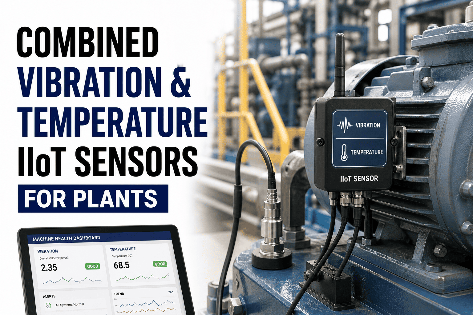
Detect imbalance, misalignment, bearing wear, looseness, and resonance in rotating machinery. Triaxial accelerometers capture fault signatures across all axes simultaneously for complete diagnostic coverage.
MotorsPumpsFansGearboxes
Detection lead time: 2 to 8 weeks before failure
02
Temperature Sensors
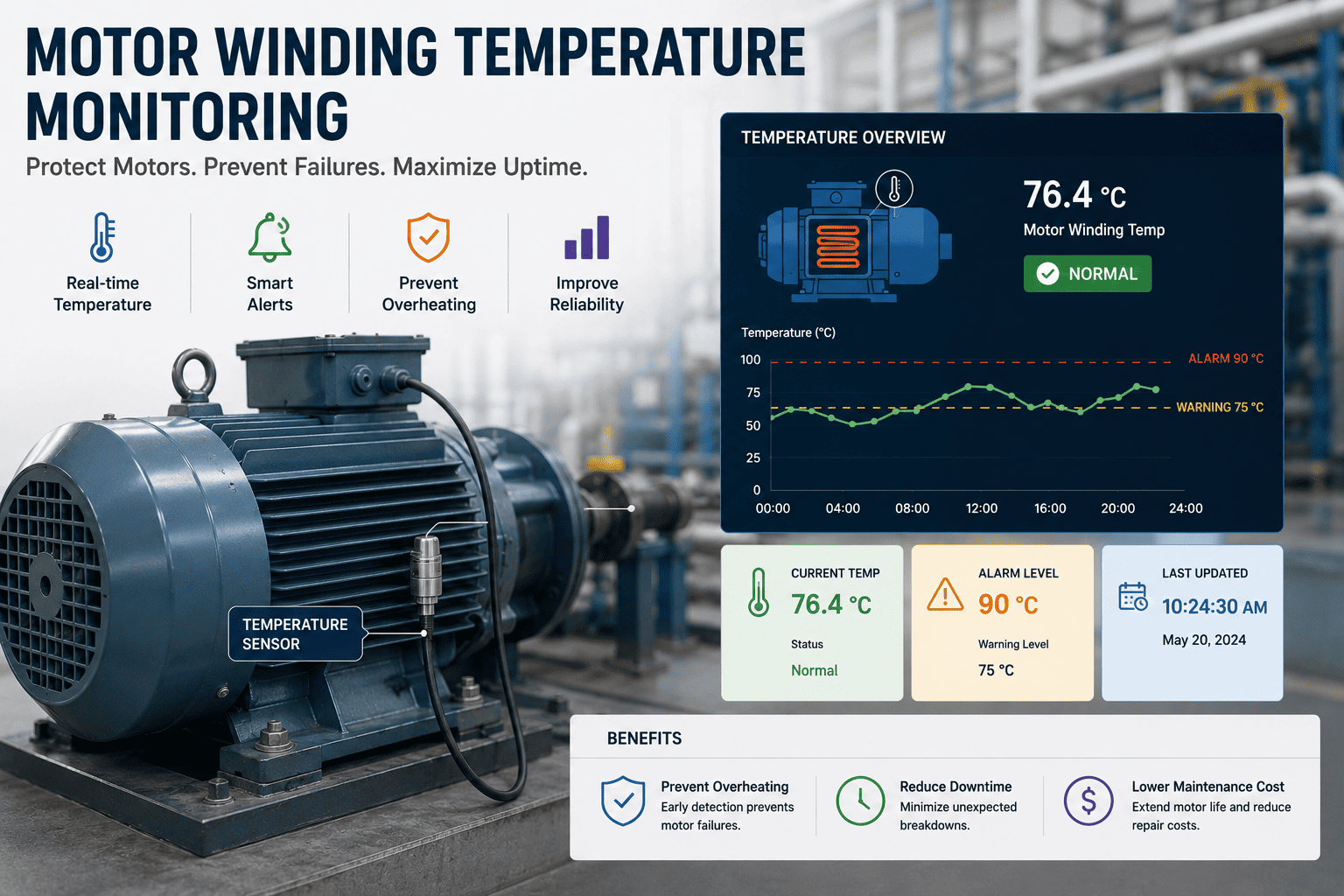
Identify thermal runaway, cooling failures, electrical overload, and bearing friction through RTDs, thermocouples, and infrared non-contact sensors mounted at critical surface points.
Electrical PanelsBearingsFurnaces
Target accuracy: ±0.5°C for bearing monitoring
03
Pressure Sensors
Monitor line pressure in hydraulic and pneumatic systems to detect blockages, leaks, pump cavitation, and flow restrictions before they cause process interruption or equipment damage.
HydraulicsPneumaticsBoilers
Operating range: 0 to 600 bar depending on process
04
Current and Power Sensors
Track electrical load, current signature, and power factor on motor-driven assets. Rotor bar damage, insulation degradation, and load imbalance appear in current waveform analysis weeks before visible symptoms emerge.
MotorsDrivesHVAC
MCSA detects faults invisible to vibration analysis alone
05
Ultrasonic Sensors
Capture high-frequency signals from 20 to 100 kHz including compressed air leaks, bearing friction, partial electrical discharge, and valve seat wear — failures invisible to vibration or temperature monitoring alone.
Compressed AirBearingsValves
Air leak detection saves up to $15,000 per year per facility
Turn Sensor Alerts Into Maintenance Actions — Automatically
Oxmaint's open API accepts data from all five sensor categories and automatically converts anomaly alerts into prioritized work orders — complete with sensor readings, asset history, timestamps, and technician assignments. No manual data entry. No missed alerts sitting in a vendor dashboard.
Sensor-to-Equipment Selection Matrix
Matching sensor type to equipment category is the most common mistake in IIoT deployment programs. Use this matrix to confirm you are monitoring each asset class with the sensors that detect its most probable failure modes — not just the sensors that were easiest to install.
Sensor Recommendation by Equipment Type
Primary First sensor to deploy for this asset class.
Secondary High value when added to primary.
Supplemental For high-criticality or complex assets.
Sensor Placement Rules That Maximize Detection Accuracy
Sensor placement determines data quality more than sensor brand or price. A correctly selected vibration sensor mounted in the wrong location produces noise, not actionable insight. These placement principles apply across all five sensor categories and directly influence the accuracy of anomaly detection in your predictive maintenance program.
01
Vibration — Bearing Housing Direct Mount
Mount accelerometers directly on the bearing housing in the radial direction (perpendicular to shaft centerline) and axial direction for thrust bearing monitoring. Stud mounting is preferred over magnet mounting for frequencies above 2 kHz. Avoid cable trays, guards, and equipment base plates as mounting surfaces — structural damping in these locations eliminates the exact signal frequencies that reveal early bearing defects.
02
Temperature — Contact Points and Hotspots
RTDs and thermocouples should be bonded at the motor winding exit, bearing outer race, or heat exchanger outlet — wherever thermal gradient is highest. For electrical panels, non-contact infrared sensors mounted at fixed standoff distances inside enclosures capture hotspots without opening energized equipment. Avoid placement where airflow creates false cooling readings near fan discharge or ventilation slots.
03
Pressure — Process Point Proximity
Install pressure sensors as close to the monitored process point as pipe routing allows. Avoid dead-end tees, long horizontal impulse lines, and locations downstream of control valves where pressure fluctuation is normal process behavior rather than a fault. For differential pressure monitoring across filters or heat exchangers, use matched impulse lines of equal length to prevent offset errors that trigger false alarms.
04
Current — Upstream of Motor Drive
Clamp-on current transformers should be placed on the motor supply cable between the motor control center and any variable frequency drive. Measuring at the motor terminal block provides the cleanest current signature for MCSA analysis. Monitor all three phases individually on three-phase motors — single-phase CT monitoring misses phase imbalance, which is the leading early indicator of insulation breakdown in industrial motors.
From Sensor Alert to Resolved Work Order — The IIoT Maintenance Pipeline
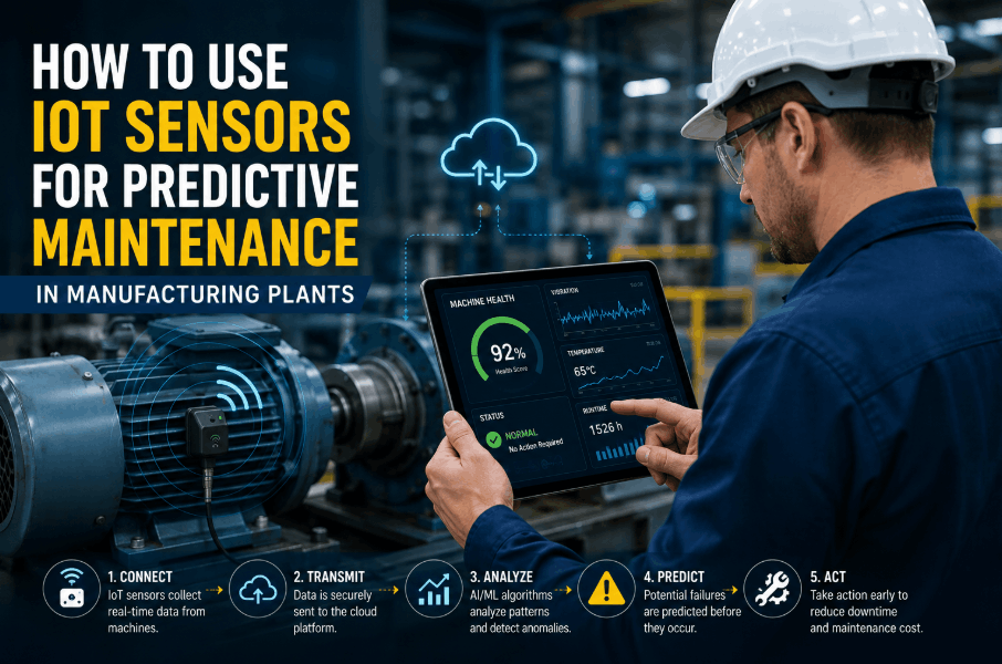
Raw sensor data has zero maintenance value until it reaches your technician as a prioritized, evidence-backed work order. The five-stage pipeline below describes exactly how Oxmaint connects industrial sensor outputs to maintenance execution — from the first threshold breach to verified repair completion.
1
Sensor Captures Continuous Readings
Vibration, temperature, pressure, current, and ultrasonic sensors stream readings at configurable intervals — from one-second high-speed sampling on rotating equipment to hourly reads on slow-changing thermal assets. Readings are tagged with asset IDs, timestamps, and location data.
2
Edge Processing Filters Noise and Detects Anomalies
On-device or gateway-level processing applies digital signal processing, FFT analysis for vibration data, and statistical baseline comparison to separate genuine fault signatures from process noise and transient events that would otherwise generate false work orders.
3
Anomaly Data Pushes to Oxmaint via API
When a threshold breach or anomaly is confirmed, the sensor platform sends the reading, timestamp, asset ID, and severity level to Oxmaint via REST API or MQTT webhook. All incoming data automatically attaches to the corresponding asset record in your facility hierarchy.
4
Oxmaint Generates a Prioritized Work Order
Based on your configurable severity thresholds, Oxmaint auto-creates a work order with sensor evidence attached, routes it to the qualified technician by skill set and shift schedule, and sets SLA-driven due dates determined by fault severity classification.
5
Technician Acts — Sensor Confirms Resolution
The technician reviews sensor evidence on the Oxmaint mobile app, completes the repair, and logs completion notes. Post-repair sensor readings confirm the fault signature has cleared — automatically closing the loop between detection and verified resolution.
ROI Benchmarks: What Industrial IoT Sensor Programs Deliver
45%
Average Maintenance Cost Reduction
Facilities with mature IIoT sensor programs report 40 to 50% lower maintenance expenditure through elimination of reactive repairs and optimized spare parts ordering driven by real-time asset condition data.
12–18 mo
Typical Payback Period
Most manufacturing facilities recover full sensor deployment costs within 12 to 18 months, driven primarily by avoided downtime events and a measurable reduction in emergency maintenance labor across critical assets.
$330K
Average Annual Savings Per Facility
Industry benchmarks from Deloitte and McKinsey place average annual savings from predictive maintenance sensor programs between $250,000 and $400,000 per mid-size manufacturing facility.
87%
Fault Detection Accuracy
AI-assisted analysis of vibration and current sensor data achieves above 85% accuracy for rotating equipment fault classification when sensor placement follows OEM mounting specifications and baseline training protocols.
Frequently Asked Questions
What is the difference between vibration sensors and accelerometers for industrial use?
Accelerometers are a category of vibration sensor that measure acceleration in one, two, or three axes — and triaxial IEPE-type accelerometers are the industry standard for rotating equipment because they capture fault signatures from all directions simultaneously. For most industrial motors and pumps, a triaxial sensor with 100 mV/g sensitivity and a frequency range of 10 Hz to 10 kHz covers the bearing defect frequencies relevant to predictive maintenance.
Connect your vibration sensor data to Oxmaint to automatically generate work orders when bearing defect frequencies exceed your configured severity thresholds.
How many IoT sensors does a typical manufacturing facility need?
A facility managing 50 to 100 critical assets typically deploys between 150 and 400 sensors depending on equipment complexity, failure consequence, and monitoring frequency requirements. The most effective approach is to start with your 20 highest-criticality assets, establish measurement baselines, collect ROI data for 90 days, then expand systematically using that data to justify the next deployment phase.
Book a planning session and our engineering team will help you define the right sensor count and deployment sequence for your specific asset inventory.
Can industrial IoT sensors operate without continuous internet connectivity?
Yes — modern IIoT sensor platforms support edge computing architectures where data is processed and stored locally before syncing to cloud or on-premise CMMS platforms when connectivity is restored. Standard protocols including MQTT, Modbus TCP, and OPC-UA allow sensor networks to operate entirely on local industrial ethernet networks and push data in batches on a defined schedule.
Oxmaint supports offline data sync from edge-based sensor deployments, ensuring no maintenance-critical data is lost during connectivity gaps or planned network maintenance windows.
What sensor accuracy specifications matter most for predictive maintenance programs?
For rotating equipment vibration monitoring, accelerometers with ±5% amplitude accuracy and flat frequency response from 10 Hz to 10 kHz cover the bearing defect frequencies of most industrial machines. Temperature sensors should deliver ±0.5°C accuracy for bearing and motor winding applications. Pressure sensors require ±0.25% full-scale accuracy for reliable cavitation detection in pump systems — higher accuracy is required for safety-critical pressure vessels.
Book a demo to discuss exact specification requirements matched to your equipment portfolio and failure modes.
How do I integrate industrial IoT sensors with an existing CMMS platform?
Most IIoT sensor gateways expose REST API endpoints or MQTT topics that CMMS platforms can subscribe to for real-time anomaly data. Oxmaint's open REST API accepts sensor readings in JSON format from any gateway or sensor cloud platform, maps incoming data to asset records using equipment IDs, and auto-generates work orders when configurable thresholds are breached — with no middleware development required for the most common sensor platforms.
Create your free Oxmaint account and test sensor data ingestion from your existing infrastructure in under 10 minutes.
Turn Every Sensor Alert Into a Completed Repair
Sensor data only delivers ROI when it reaches the right technician at the right time — as an actionable, evidence-backed work order, not a reading buried in a vendor dashboard. Oxmaint connects vibration, temperature, pressure, current, and ultrasonic sensor outputs to prioritized work orders with asset history and technician assignments handled automatically. No spreadsheets. No missed alerts. No unplanned downtime from data nobody acted on.