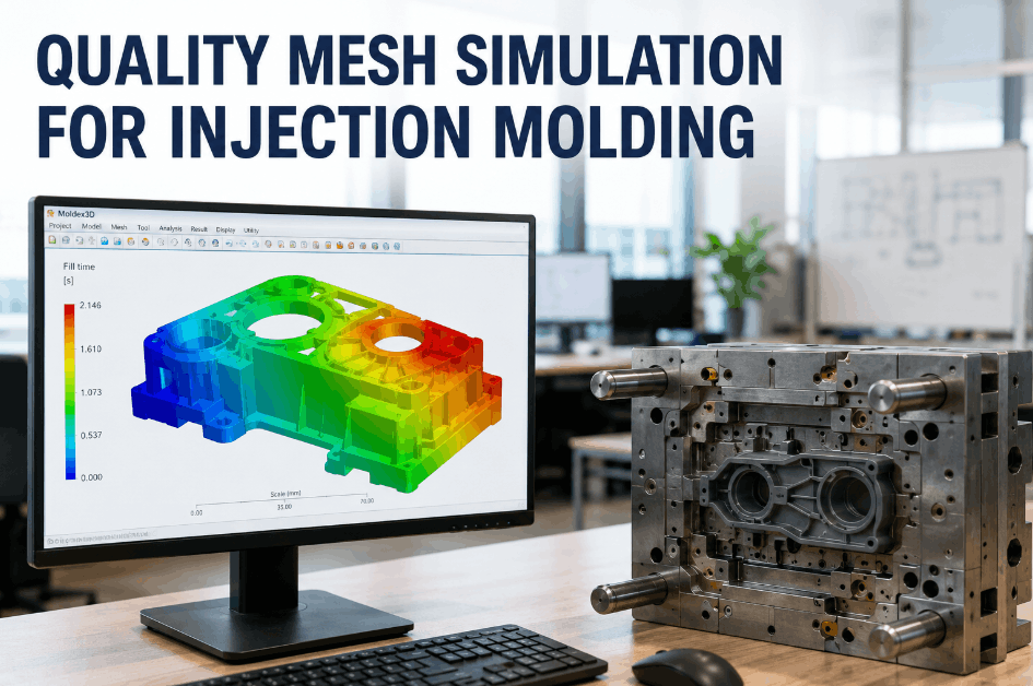
Injection molding defects rarely announce themselves before a production run begins — they appear as rejects, rework, and scrap after tooling has already cycled. Quality mesh simulation changes the timing of that discovery by running mold flow, cooling balance, and pressure variation analysis in a digital environment before the first shot is made. Sign Up Free on Oxmaint and connect simulation validation checkpoints to your work order and inspection management system so quality findings from simulation are tracked through to corrective action and production sign-off. Molding teams that integrate simulation into their process validation workflow reduce first-article failure rates, shorten mold qualification cycles, and give quality engineering the documented basis needed for tooling approval decisions. Book a Demo to see how Oxmaint supports quality inspection workflows and defect tracking for injection molding and process manufacturing environments.
What Quality Mesh Simulation Models in Injection Molding
A quality mesh represents the cavity, runner system, gate locations, and cooling channels of a mold tool in a computational model. Simulation engines solve for flow front behavior, pressure distribution, temperature gradients, and shrinkage profiles — each of which maps directly to a class of physical defects that appear in production. Sign Up Free on Oxmaint to establish inspection checkpoints tied to simulation-identified risk zones so quality engineers can validate whether simulation predictions are confirmed or contradicted by first-article results.
Simulates how polymer melt travels from gate to extremities across the cavity. Flow analysis identifies weld line locations, air trap risk zones, hesitation points, and short-shot probability at current injection parameters — before tooling is cut or process parameters are finalized.
Models heat transfer from the melt through the part geometry and into cooling channels. Cooling imbalance produces warpage, differential shrinkage, and extended cycle times. Simulation identifies regions where cooling channel placement, flow rate, or circuit configuration is insufficient before tool construction commits to the current design.
Calculates cavity pressure distribution from gate to last-fill location. Excessive pressure drop produces sink marks, voids, and dimensional inconsistency. Pressure variation mapping identifies gate size, runner balance, and injection speed parameters that equalize pressure distribution across single and multi-cavity tools.
Calculates differential volumetric shrinkage across the part geometry at defined process conditions. Warpage prediction identifies whether dimensional tolerance requirements can be met at current tool design — and which geometry modifications or process parameter adjustments reduce out-of-tolerance risk before production launch.
Defect Scenario Mapping: Simulation Prediction to Physical Failure Mode
The value of quality mesh simulation depends on how systematically simulation predictions are connected to the defect scenarios teams are managing in production. Book a Demo to see how Oxmaint's inspection and quality tracking tools support defect scenario documentation and corrective action management across molding production environments.
| Simulation Finding | Physical Defect Risk | Severity | Recommended Corrective Action | Validation Method |
|---|---|---|---|---|
| Weld line at structural zone | Reduced tensile strength at knit line | High | Gate relocation or material change | Tensile testing on first articles |
| Air trap in blind geometry | Burn marks, voids, short shots | High | Vent addition or gate repositioning | Visual inspection + cross-section |
| Cooling imbalance >15°C delta | Warpage, differential shrinkage | Medium–High | Cooling circuit redesign | CMM dimensional check |
| Pressure drop >80% at last fill | Sink marks, voids, incomplete fill | High | Gate enlargement or runner rebalance | Fill study at molding trial |
| Hesitation at thin wall section | Surface blemish, flow line | Medium | Injection speed profile adjustment | Visual cosmetic inspection |
| Over-pack near gate | Flash, dimensional oversize, stress | Medium | Pack pressure profile reduction | Dimensional measurement + flash check |
Integrating Quality Mesh Simulation Into Your Process Validation Workflow
Run Simulation at Design Freeze, Not Tooling Approval
The optimal simulation timing is at part design freeze — when gate location, wall thickness, and material selection are confirmed but tooling construction has not begun. Running simulation after tool approval limits corrective options to process parameter adjustments; running it before allows geometry and tool design changes that eliminate defect risk rather than manage it.
Document Simulation Findings as Inspection Checkpoints
Convert each simulation-identified risk zone into a named inspection checkpoint for first-article and production sampling plans. This creates a direct link between simulation prediction and production verification — and gives quality engineers the documented rationale for why specific inspection locations were selected.
Test Process Scenarios Digitally Before Molding Trials
Use simulation to compare multiple process scenarios — different injection speeds, pack profiles, and melt temperatures — before committing machine time to physical trials. Each simulated scenario generates predicted defect outcomes for that parameter set, allowing teams to enter molding trials with an informed starting parameter window rather than a broad experimental range.
Compare Simulation Predictions Against First-Article Results
After molding trials, systematically compare simulation predictions to first-article inspection findings. Confirmed predictions validate the simulation model for that tool geometry. Discrepancies identify where material data, boundary conditions, or model assumptions need refinement — improving prediction accuracy for future simulations on similar part families.
Archive Simulation Reports in Your Quality Management System
Store simulation reports, defect scenario analyses, and corrective action records as part of the tooling qualification package. Oxmaint's document management and work order history gives quality teams a retrievable record of validation decisions that supports customer audits, PPAP submissions, and future tool modification reviews.