Vibration is the language machines speak when something is wrong — and in power plants, where boiler feed pumps, condensate extraction pumps, forced draft fans, induced draft fans, cooling tower fans, and turbine-generator trains run continuously under massive thermal and mechanical loads, that language can be the difference between a planned outage and a catastrophic bearing failure that takes a unit offline for weeks. ISO 10816 and ISO 20816 define the vibration severity limits that separate acceptable operation from equipment-damaging territory. But the standard means nothing without a structured route — a repeatable set of measurement points, acceptance criteria, trend baselines, and escalation triggers that your reliability team executes consistently. This free power plant vibration route template gives you a field-ready starting point for BFP trains, fans, motors, and critical rotating plant, with ISO 10816 velocity and displacement limits, measurement point definitions, and CMMS-tracked records. Start your free Oxmaint account to manage vibration routes alongside your full PM program.
Why a Structured Vibration Route Pays for Itself
Catch Bearing Failures 4–6 Weeks Early
Defect-frequency vibration signatures appear weeks before catastrophic failure. A route that captures trend data lets your team plan bearing replacement during scheduled outage windows — not emergency shutdowns.
Validate Alignment and Balance After Repairs
Post-maintenance vibration testing confirms that alignment, coupling, and balance work was done correctly before the unit is returned to service. A baseline measurement on day one is your quality acceptance test.
Avoid ISO 10816 Exceedances and Warranty Voids
Operating rotating equipment above ISO 10816 Class C limits accelerates bearing, seal, and impeller wear. Many OEM warranties are voided if the machine is operated outside vibration limits without documented corrective action.
Build Trend History That Justifies Capital Decisions
When management asks why a $200,000 BFP needs replacement, a 24-month vibration trend showing progressive deterioration is a far stronger business case than a technician's verbal assessment.
ISO 10816 Vibration Severity — Quick Reference for Power Plant Equipment
ISO 10816 classifies machines into groups based on power rating and mounting type. Power plant rotating equipment predominantly falls into Class II (medium-sized machines, 15 – 75 kW) and Class III / IV (large machines above 75 kW, rigidly and flexibly mounted). Use the table below as your acceptance threshold reference on each route sheet.
Zone A — New / Recently maintained. Unrestricted operation.
Zone B — Acceptable for long-term operation.
Zone C — Alarm — investigate before next scheduled maintenance.
Zone D — Danger — shut down for assessment.
| Machine Class |
Typical Equipment |
Zone A (mm/s RMS) |
Zone B (mm/s RMS) |
Zone C (mm/s RMS) |
Zone D (mm/s RMS) |
| Class I (<15 kW) |
Small pumps, fans, lube oil equipment |
0.71 |
1.8 |
4.5 |
>4.5 |
| Class II (15–75 kW) |
Condensate pumps, small motors, auxiliary fans |
1.12 |
2.8 |
7.1 |
>7.1 |
| Class III — Rigid (>75 kW) |
BFP motors, FD/ID fans, CEP, CWP |
1.8 |
4.5 |
11.2 |
>11.2 |
| Class III — Flexible (>75 kW) |
BFP with flexible coupling, VFD-driven fans |
2.8 |
7.1 |
18.0 |
>18.0 |
| Class IV — Large Machines |
Turbine-generators, large BFP trains |
3.5 |
7.1 |
11.2 |
>11.2 |
All values in mm/s RMS per ISO 10816-1. Consult OEM documentation for machine-specific limits which may be more restrictive than the ISO class default.
Spreadsheet-based vibration routes lose trend context — fast.
Oxmaint links every vibration reading to an asset, maintains rolling trend history, and flags Zone C and D exceedances for immediate engineering review — all from the field technician's mobile device.
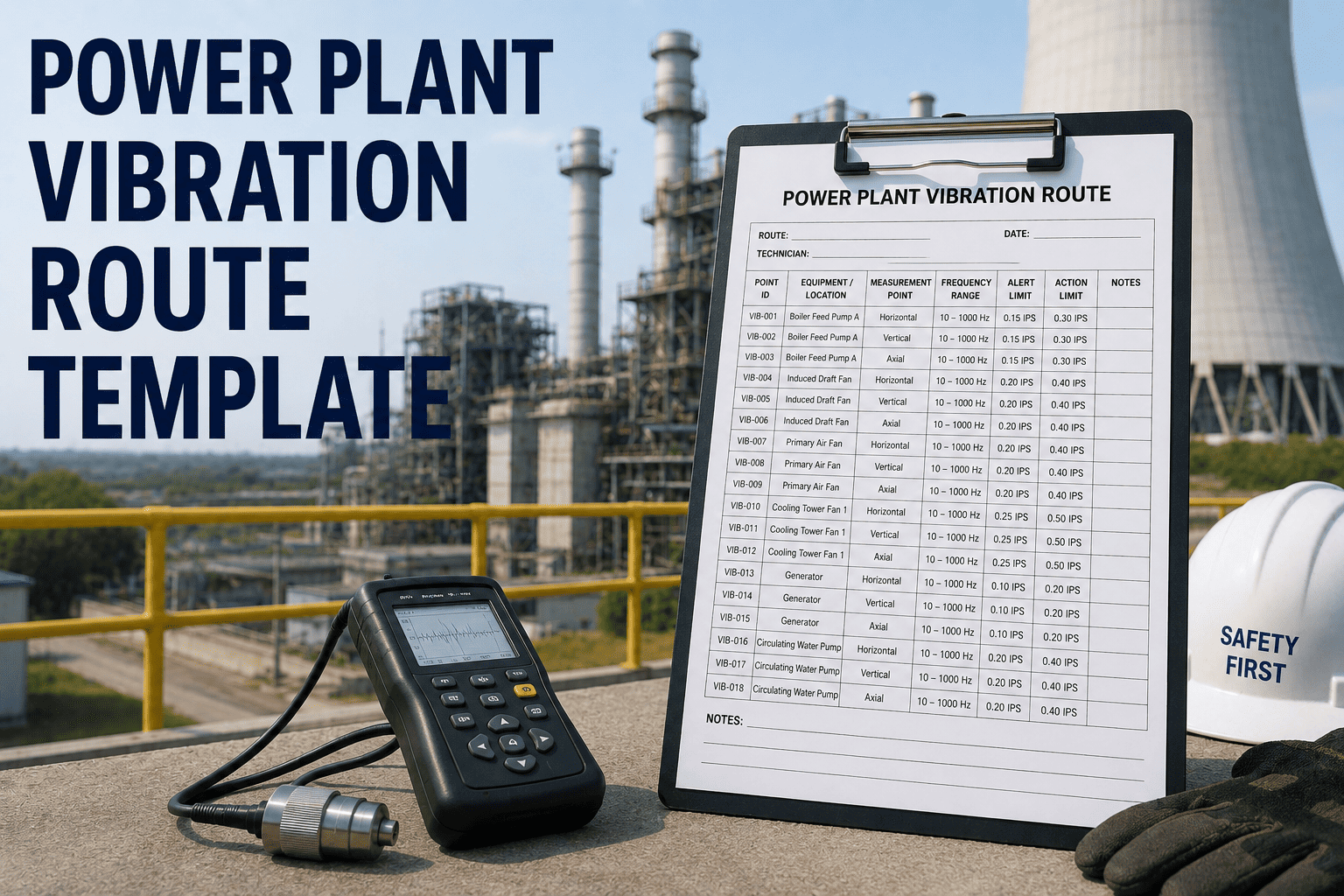
Power Plant Vibration Route Template
Use one route sheet per equipment train. Record each measurement at the defined point location, in the specified direction, at the stated operating condition. Any Zone C or D reading must be escalated to the reliability engineer before leaving the field — not documented and filed for later review.
Boiler Feed Pump (BFP) Train — Measurement Points
| Point ID |
Location |
Direction |
Parameter |
Zone A Limit |
Zone C Alert |
Reading (mm/s) |
Zone |
Baseline |
Trend |
| BFP-M-DE-H |
Motor — Drive End Bearing |
Horizontal |
Velocity RMS |
1.8 |
11.2 |
_______ |
[A/B/C/D] |
_______ |
[Up/Stable/Down] |
| BFP-M-DE-V |
Motor — Drive End Bearing |
Vertical |
Velocity RMS |
1.8 |
11.2 |
_______ |
[A/B/C/D] |
_______ |
[Up/Stable/Down] |
| BFP-M-NDE-H |
Motor — Non-Drive End |
Horizontal |
Velocity RMS |
1.8 |
11.2 |
_______ |
[A/B/C/D] |
_______ |
[Up/Stable/Down] |
| BFP-M-NDE-V |
Motor — Non-Drive End |
Vertical |
Velocity RMS |
1.8 |
11.2 |
_______ |
[A/B/C/D] |
_______ |
[Up/Stable/Down] |
| BFP-P-DE-H |
Pump — Drive End Bearing |
Horizontal |
Velocity RMS |
1.8 |
11.2 |
_______ |
[A/B/C/D] |
_______ |
[Up/Stable/Down] |
| BFP-P-DE-V |
Pump — Drive End Bearing |
Vertical |
Velocity RMS |
1.8 |
11.2 |
_______ |
[A/B/C/D] |
_______ |
[Up/Stable/Down] |
| BFP-P-NDE-H |
Pump — Non-Drive End |
Horizontal |
Velocity RMS |
1.8 |
11.2 |
_______ |
[A/B/C/D] |
_______ |
[Up/Stable/Down] |
| BFP-P-AX |
Pump — Drive End |
Axial |
Velocity RMS |
1.8 |
11.2 |
_______ |
[A/B/C/D] |
_______ |
[Up/Stable/Down] |
Forced Draft (FD) Fan & Induced Draft (ID) Fan
| Point ID |
Location |
Direction |
Parameter |
Zone A Limit |
Zone C Alert |
Reading (mm/s) |
Zone |
Baseline |
Trend |
| FDF-M-DE-H |
FD Fan Motor — Drive End |
Horizontal |
Velocity RMS |
2.8 |
11.2 |
_______ |
[A/B/C/D] |
_______ |
[Up/Stable/Down] |
| FDF-M-NDE-H |
FD Fan Motor — Non-Drive End |
Horizontal |
Velocity RMS |
2.8 |
11.2 |
_______ |
[A/B/C/D] |
_______ |
[Up/Stable/Down] |
| FDF-FN-DE-H |
FD Fan Shaft — Drive End Bearing |
Horizontal |
Velocity RMS |
2.8 |
11.2 |
_______ |
[A/B/C/D] |
_______ |
[Up/Stable/Down] |
| FDF-FN-NDE-H |
FD Fan Shaft — Non-Drive End |
Horizontal |
Velocity RMS |
2.8 |
11.2 |
_______ |
[A/B/C/D] |
_______ |
[Up/Stable/Down] |
| IDF-M-DE-H |
ID Fan Motor — Drive End |
Horizontal |
Velocity RMS |
2.8 |
11.2 |
_______ |
[A/B/C/D] |
_______ |
[Up/Stable/Down] |
| IDF-FN-DE-H |
ID Fan Shaft — Drive End Bearing |
Horizontal |
Velocity RMS |
2.8 |
11.2 |
_______ |
[A/B/C/D] |
_______ |
[Up/Stable/Down] |
Observation Notes & Escalation
Abnormal Observations (Record Any)
Unusual noise (describe): _________________________
Visible looseness / resonance: _________________________
Hot bearing housing (temperature): _________________________
Oil leakage at seals: _________________________
Coupling guard condition: _________________________
Escalation Action Required
No Zone C or D readings — route complete, close WO
Zone C reading — notify reliability engineer before closing WO
Zone D reading — escalate to shift supervisor for shutdown decision
Trend worsening >20% vs last route — flag for analysis
Work order opened for corrective action — WO No.: ___________
Technician Sign-Off________________________ Date/Time: ___________
Reliability Engineer Review________________________ Date/Time: ___________
Vibration Measurement Best Practices for Power Plant Technicians
01
Measure at the Same Load Every Time
Vibration amplitude changes significantly with load. A BFP at 60% flow will read differently than at 95% flow. Record operating load on every route sheet and compare measurements only at equivalent load conditions.
02
Mark Measurement Points Physically
Use paint markers or stickers to permanently mark transducer placement points on each bearing housing. Point-to-point variation in sensor position creates false trend shifts that can mask or mimic real deterioration.
03
Allow Equipment to Stabilize Before Measuring
Wait at least 20 to 30 minutes after startup or load change before taking route measurements. Thermal transients and startup loads can produce elevated readings that do not reflect steady-state equipment health.
04
Record All Three Directions on Critical Equipment
Horizontal, vertical, and axial measurements reveal different fault types. Misalignment shows strongly in the axial direction; imbalance dominates in horizontal and vertical. Single-direction routes miss important diagnostic information.
05
Compare to Trend, Not Just Limits
A reading of 5 mm/s in Zone B is safe — unless it was 1.5 mm/s six months ago. Rate of change is often a more useful indicator than absolute value. Always record and compare against the previous route reading and the commissioned baseline.
06
Verify Instrument Calibration Before the Route
A miscalibrated meter can make a sick machine look healthy or a healthy machine look alarming. Verify meter calibration at the start of every route — not just annually. Field calibration checks take two minutes and protect months of trend data integrity.
Frequently Asked Questions
How often should vibration routes be run on power plant rotating equipment?
Critical equipment — BFPs, ID/FD fans, CEPs — typically runs monthly routes at minimum. Less critical auxiliary equipment may run quarterly. High-hours or aging equipment benefits from bi-weekly routes when trending toward Zone C. The frequency should be driven by equipment criticality, historical failure patterns, and operating hours — not calendar convenience.
Oxmaint can schedule route frequencies per asset based on your criticality matrix.
What is the difference between velocity-based and acceleration-based vibration measurement?
Velocity (mm/s RMS) is most sensitive in the low-to-mid frequency range (10–1000 Hz) and is the standard parameter for ISO 10816 severity assessment of overall machine health. Acceleration (g RMS or enveloped acceleration) is more sensitive at high frequencies and is used for early-stage bearing defect detection. Power plant route sheets should capture both where possible — velocity for ISO compliance and trend, acceleration enveloping for bearing condition monitoring.
What does a rapid increase in axial vibration on a BFP typically indicate?
A rapid rise in axial vibration at the BFP pump bearing is most commonly associated with thrust bearing wear, misalignment at the coupling, or impeller erosion affecting axial load balance. It can also indicate cavitation at low-flow conditions. Any axial reading that increases more than 30% between routes on a BFP should be escalated immediately to the reliability engineer for spectrum analysis.
Talk to our team about integrating spectrum analysis workflows with Oxmaint route data.
Should baseline measurements be taken at commissioning or after the first overhaul?
Both. A commissioning baseline establishes the machine's "as-new" vibration signature for all future comparisons. A post-first-overhaul baseline captures the as-repaired condition and is often the more meaningful long-term reference, since many components settle in after initial operation. Record both, label them clearly in your CMMS, and use the most recent post-maintenance measurement as the active comparison baseline.
How does Oxmaint support vibration route management in a power plant?
Oxmaint lets you create recurring work orders for each vibration route, assign them to technicians with measurement point instructions, capture readings on mobile with automatic Zone A–D classification, and flag Zone C and D readings for immediate review. All readings are stored against the asset record with timestamps and technician sign-off, creating a complete trend history that is always available for reliability analysis and audit.
Sign up free and build your first vibration route in minutes.
Turn Every Vibration Reading Into an Early Warning System
The most expensive vibration data is the data that was never collected. A structured route program on your critical rotating equipment — BFPs, fans, motors — turns routine measurements into an early warning system that catches bearing failures, misalignment, and imbalance before they become unit-stopping events. Start with this template. Build the trend. Let Oxmaint track it.