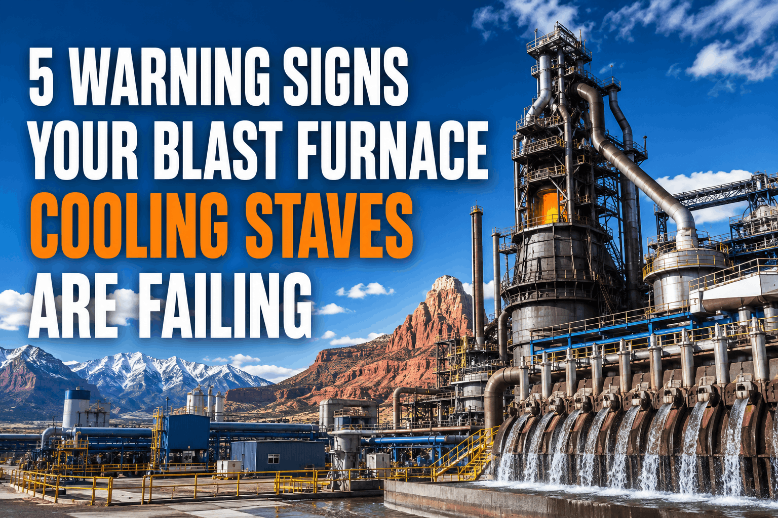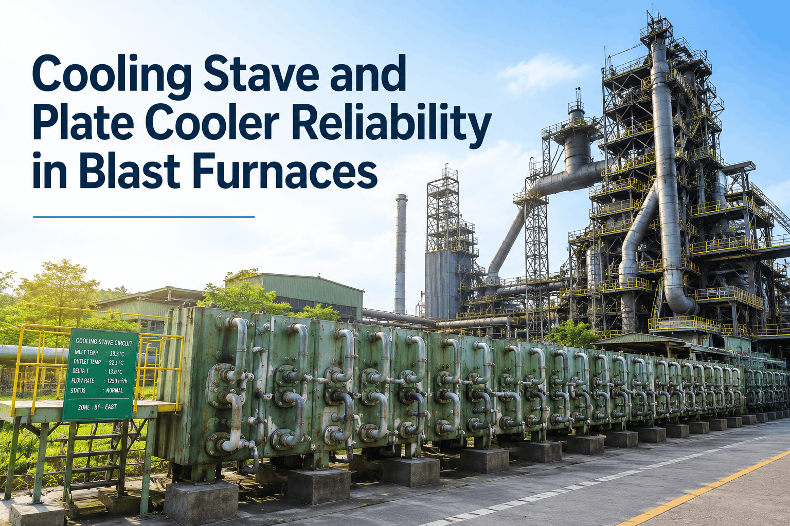
A blast furnace cooling system quietly carries 30–50 MW of heat load away from the shell every single operating hour, and a single failed stave cooler can trigger an unplanned blowdown that costs upward of $1.2M per day in lost hot metal production. This guide translates field experience into a practical maintenance playbook: stave cooler inspection intervals, cooling water circuit monitoring thresholds, heat-flux trending logic, and water quality management targets that actually extend campaign life beyond the 15-year mark. The framework aligns with ISO 55000 asset-management principles and TPM autonomous-maintenance routines. If your team is ready to digitize the entire workflow — from ultrasonic thickness readings to CMMS work-order automation — you can Start Free Trial and configure cooling-system templates in under an hour.
Is your stave cooler one thermal spike away from a campaign-ending failure?
Over 70% of premature blast furnace relines trace back to undetected stave cooler degradation — gas leakage, erosion, or scale fouling that progressed silently for months. The right inspection cadence and heat-flux trending can push campaign life past 18 years and cut unplanned cooling-related downtime by up to 60%.
CAMPAIGN LIFE WITH
PROACTIVE STAVE COOLER MANAGEMENT
Four circuits, one thermal balance — where failures actually begin
A typical 3,800 m³ blast furnace runs 360–420 plate staves across bosh, belly, and lower stack zones, served by four parallel cooling circuits. Each circuit behaves differently under load — and each fails through a distinct mechanism. Understanding the failure mode per zone is the first step toward a defensible inspection plan.
Furnace Shell Spray
External spray cooling on the shell. Low heat flux (5–15 kW/m²) but corrosion under scale is the silent killer. Inspect nozzle patterns weekly; flow deviation beyond ±8% signals blockage.
Stave Cooler Circuit
Cast-iron or copper staves with internal pipes. Highest heat flux (40–120 kW/m² in the bosh). Gas leakage behind staves and pipe erosion account for ~58% of all cooling failures.
Tuyere Cooling
High-velocity copper tuyeres at 2,100°C flame face. Heat flux spikes to 350 kW/m². A single tuyere burnout costs $45K–$90K and 4–8 hours of reduced blast volume.
Hearth Cooling
Bottom plate and sidewall staves protect the hearth refractory. Thermal load is steady (10–25 kW/m²) but salamander growth and carbon erosion make this the highest-consequence circuit for campaign life.
The stave cooler inspection protocol that catches failure 6–10 weeks early
Field data from 40+ integrated steel mills shows that a disciplined inspection regime identifies 85% of stave cooler failures 6–10 weeks before they escalate. The checklist below is organized by frequency — each tier maps to a specific TPM autonomous-maintenance or planned-maintenance role.
- Verify ΔT across each stave cooler outlet — flag any reading beyond ±3°C from 24-hour rolling average
- Log cooling water flow rate per circuit; deviation >5% from baseline triggers an amber alert
- Inspect shell surface for hot spots above 90°C using thermal imaging — any spot above 120°C is a red alert
- Check stave gas-leakage ports for water seepage or steam emission
- Verify standpipe water level and overflow continuity on the seal valve
- Record tuyere nose temperature profile — any reading above 280°C requires immediate flow increase
- Calculate heat flux per stave: Q = (m_dot × Cp × ΔT) ÷ A — trend against 4-week rolling baseline
- Sample cooling water at circuit returns — total hardness must stay below 80 ppm as CaCO₃
- Inspect flange bolt torque on stave supply and return pipework — log any torque loss beyond 15%
- Run ultrasonic thickness (UT) spot checks on 10% of bosh stave pipe bends — erosion rate beyond 0.3 mm/yr is critical
- Review CMMS open work orders for cooling system tags — close or escalate any item older than 14 days
- Build a full heat-flux contour map of the furnace shell — compare to previous month and to start-of-campaign baseline
- Perform borescope inspection of accessible stave pipe internals where isolation valves permit
- Conduct dissolved-oxygen and chloride analysis on cooling water — O₂ above 0.05 ppm or Cl⁻ above 50 ppm accelerates pitting
- Review feedwater treatment logs — confirm phosphate, zinc, and dispersant dosing stayed within target bands 95% of the time
- Run a FMEA review on any circuit that logged two or more amber alerts in the period
The formula that turns cooling water data into a failure-prediction signal
Heat flux is the single most powerful leading indicator of stave cooler health. When calculated per stave and trended against a rolling baseline, a sustained 25% rise in flux with no corresponding hot-blast parameter change is a reliable 4–8 week precursor to pipe rupture or gas leakage. Below is the core formula, the alert thresholds, and the condition-mapping logic.
| Stave Zone | Normal Heat Flux (kW/m²) | Amber Alert | Red Alert / Action | Primary Failure Mode |
|---|---|---|---|---|
| Upper Stack | 8 – 20 | +30% sustained 7 days | +50% — isolate & UT inspect | Refractory wear, gas channeling |
| Belly | 20 – 45 | +25% sustained 5 days | +40% — reduce burden, inspect | Stave pipe erosion, scale fouling |
| Bosh | 40 – 120 | +20% sustained 48 hrs | +35% — emergency stave isolation | Pipe rupture, cast-iron cracking |
| Hearth Sidewall | 10 – 25 | +25% sustained 7 days | +40% — review salamander level | Carbon block erosion, hot metal breakout |
| Tuyere Zone | 200 – 350 | +15% sustained 12 hrs | +25% — swap tuyere at next window | Copper burnout, refractory integrity |
A 6-month stave cooler maintenance roadmap that pays for itself
At a 2.8 MTPA integrated mill, a single unplanned BF shutdown for stave replacement costs $3.8M–$6.2M in lost production. A structured 6-month proactive plan — built on the inspection protocol above — typically costs $85K–$140K in labor, NDT, and water-treatment chemistry, and prevents 1–2 major failures per campaign. Here is the month-by-month roadmap.
Establish full-circuit baseline and digitize CMMS records
Install or verify flow and temperature sensors on all stave circuits. Backfill 12 months of manual logs into the CMMS. Calculate per-stave baseline heat flux and publish the contour map. Identify the bottom 10% of staves by condition for priority monitoring.
Reset water chemistry to target bands and validate dosing
Conduct a full water audit — hardness, alkalinity, chloride, dissolved oxygen, pH, and conductivity. Calibrate dosing pumps and set high/low alarms in the SCADA. Target: hardness <80 ppm CaCO₃, Cl⁻ <50 ppm, O₂ <0.05 ppm. Document baseline for monthly comparison.
Execute UT thickness survey on 100% of bosh and belly stave pipes
Mobilize NDT crew for a full ultrasonic thickness campaign on all accessible stave pipe bends and straight runs. Log minimum wall thickness per stave into the CMMS. Flag any stave below 3.5 mm wall (or erosion rate >0.3 mm/yr) for quarterly re-measurement. Cross-reference with heat-flux anomalies.
Publish first quarterly heat-flux trend report and FMEA update
Aggregate 90 days of sensor data into a stave-level trend report. Run a formal FMEA on any circuit with amber alerts. Update the criticality rating of each stave in the CMMS. Schedule any planned stave isolation or blowdown for the next blast-stop window.
Execute planned stave isolations, gasket replacements, and pipe repairs
During the scheduled 8–12 hour blast stop, isolate and repair the top-priority staves identified in M4. Replace degraded gaskets, re-torque flanges, and clear any blocked cooling passages. Re-commission with a 24-hour intensified monitoring protocol.
Verify post-maintenance improvement and lock the recurring schedule
Compare post-M5 heat-flux readings against the M1 baseline — target a 10–20% reduction in outlier staves. Confirm water chemistry remains within band. Lock the daily/weekly/monthly inspection cadence into the CMMS as auto-generated work orders for the next 12 months.
A 2.8 MTPA mill: $4.1M saved by catching one bosh stave failure 8 weeks early
Consider a 2.8 MTPA integrated steel plant operating a 3,800 m³ blast furnace with 384 stave coolers. Before implementing a structured cooling maintenance program, the plant averaged 1.4 unplanned cooling-related shutdowns per year at $3.2M each. After deploying the inspection protocol and heat-flux trending described above within a digital CMMS, the plant caught a bosh stave pipe erosion failure 8 weeks before rupture during a routine UT survey — and repaired it during a planned 10-hour blast stop.
The heat-flux trend on stave B-23 had been creeping up for three weeks before our UT crew confirmed pipe wall erosion. We swapped the stave during a planned stop instead of losing the furnace for four days. That single catch paid for the entire CMMS rollout.
Stop discovering stave failures during blowdowns
Deploy a digital cooling-system maintenance workflow in under an hour. Auto-generate inspection rounds, track heat-flux trends per stave, and turn NDT readings into predictive work orders.
Stave cooler maintenance — the questions reliability teams ask most
What is the ideal cooling water flow velocity inside a blast furnace stave cooler pipe?
The recommended flow velocity is 1.5–2.5 m/s. Below 1.5 m/s, sediment and scale deposit in horizontal runs, accelerating under-deposit corrosion. Above 3.0 m/s, erosion-corrosion on pipe bends — especially at the bosh zone — can exceed 0.4 mm/year. Velocity should be verified during every quarterly audit and adjusted via circuit balancing valves, not by throttling individual stave supplies.
How often should stave cooler wall thickness be measured ultrasonically?
A full UT thickness survey of all accessible stave pipe bends and straights should be conducted at least once per year on a furnace in mid-to-late campaign (years 8+). For furnaces in early campaign (years 1–7), a representative 30% sample every 18 months is sufficient. Any stave flagged with wall thickness below 4.0 mm or an erosion rate above 0.3 mm/yr should move to a quarterly re-measurement cadence. You can automate the scheduling and trending of these readings by deploying a Start Free Trial of the OxMaint CMMS, which ships with stave-cooler inspection templates out of the box.
What water quality parameters most directly impact stave cooler longevity?
The four parameters that matter most are total hardness (keep below 80 ppm as CaCO₃ to prevent scale), chloride concentration (below 50 ppm to avoid pitting in copper and cast iron), dissolved oxygen (below 0.05 ppm to suppress corrosion), and pH (maintain 8.0–9.0). Beyond chemistry, suspended solids should stay below 10 ppm — fouling on internal pipe surfaces reduces heat transfer and drives up local wall temperatures, which accelerates every failure mode simultaneously.
Can a failed stave cooler be isolated without shutting down the blast furnace?
Yes, in most cases. A single stave can be isolated by closing its supply and return valves and blanking the connection, provided the surrounding staves can absorb the additional thermal load. Operations should immediately reduce blast volume by 3–8% and increase cooling flow to adjacent staves by 10–15%. However, isolating more than 2–3 staves in the same zone risks localized shell overheating and refractory damage — at that point a planned blast stop for repair is the safer path.
How does a CMMS specifically improve blast furnace cooling maintenance?
A CMMS transforms cooling maintenance in three concrete ways: it auto-generates daily, weekly, and monthly inspection rounds against each stave and circuit so nothing is missed; it stores every UT reading, flow log, and water sample result against the specific asset for longitudinal trending; and it triggers predictive work orders when heat-flux or wall-threshold thresholds are breached. To see a stave-cooler workflow configured live for your furnace, Book a Demo and the team will map your circuit layout into the platform during the session.
Give your cooling system the discipline it demands
Build your stave cooler inspection protocol, heat-flux trending dashboards, and water-quality alerting in a single platform — designed for metallurgical asset reliability teams.
Free 14-day trial · No credit card