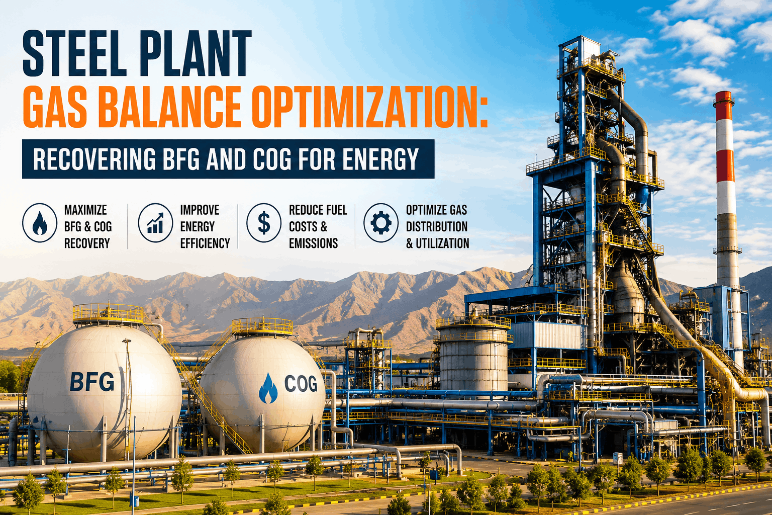
By-product gases — blast furnace gas, coke oven gas, and LD converter gas — account for approximately 30% of total energy consumption in an integrated steel plant. With only 25% of residual heat currently recovered across the industry, the gap between what most plants flare and what best-in-class plants recover represents one of the largest untapped cost reduction opportunities in steelmaking. OxMaint's Energy Analytics and Gas Monitoring platform gives energy teams the real-time visibility to close that gap.
Steel Plant Gas Balance Optimization: BFG, COG & LDG Distribution and Recovery
A technical reference for energy managers and plant engineers covering calorific management, gas holder operations, flare minimization, and boiler fuel optimization across the integrated steel plant gas network.
Understanding the Three By-Product Gases
Effective gas balance management starts with understanding what each gas is, how it behaves, and where it can and cannot substitute for natural gas or each other. Calorific value, CO content, and supply intermittency differ substantially across BFG, COG, and LDG — and mismatching gas type to consumer is the most common root cause of inefficient combustion, burner damage, and unnecessary flaring.
Blast Furnace Gas
Generated continuously from iron reduction in the blast furnace. Low calorific value fuel with very high CO content — the primary safety hazard in the gas network.
Coke Oven Gas
Generated during coal carbonization in coke ovens. High calorific value with significant hydrogen content — the premium fuel in the steel plant gas network and a critical enrichment agent for BFG.
LD Converter Gas (LDG)
Generated during the oxygen blowing stage in the basic oxygen furnace. Highly intermittent supply in large bursts during the blow, followed by zero generation between heats — the most challenging gas to buffer and distribute.
Gas Holder Management: The Buffer Between Production and Consumption
Gas holders (gasometers) are the pressure and volume buffers that decouple gas production from consumption in the distribution network. Without properly functioning gas holders, any mismatch between supply and demand goes directly to the flare. Gas holder availability is the single most important mechanical factor in flare minimization.
Operating Level Management
Each gas holder should operate within a defined working band — typically 20% to 80% of total volume — leaving headroom to absorb supply surges and buffer stock to cover demand peaks. Operating chronically near high or low limits eliminates the buffer function and forces flaring or curtailment.
Seal System Maintenance (Oil-Seal and Water-Seal Types)
Oil-seal gasometers (common for BFG and COG) depend on maintained oil level and oil quality to prevent gas bypass. Water-seal gasometers (common for LDG) require monitored water level and corrosion protection. Both types require regular seal integrity checks — seal failure transfers directly to atmospheric gas release.
Pressure and Flow Instrumentation
Accurate holder level and gas flow measurement is the foundation of gas balance management. Drift in level transmitters causes incorrect dispatch decisions — over-consuming when the holder reads high, flaring when it reads low. Instrument calibration is not optional.
Monitor gas holder levels, calorific values, and flare events in real time with OxMaint Energy Analytics.
Gas Mixing and Calorific Value Control at the Mixing Station
BFG has a calorific value of 3 to 4 MJ/m³ — too low for direct firing in reheating furnaces without enrichment. The gas mixing station is where BFG is blended with COG or LDG to reach the calorific value required by each downstream consumer. Maintaining target CV at the mixing point directly controls furnace efficiency, burner stability, and NOx formation.
| Consumer | Minimum CV Required | Typical Gas Mix | Key Control Parameter |
|---|---|---|---|
| Hot blast stoves | 3–4 MJ/m³ | BFG only or BFG + trace COG | Blast furnace top pressure stability |
| Power boilers | 3.5–5 MJ/m³ | BFG enriched with COG or LDG | Steam pressure response to CV drop |
| Reheating furnaces | 7–10 MJ/m³ | BFG + COG or COG + LDG mix | Wobbe index stability for burner management |
| Coke oven batteries | 16–20 MJ/m³ | COG direct | Underfiring temperature uniformity |
| Annealing furnaces | 8–12 MJ/m³ | COG + BFG or COG + LDG | Atmosphere composition as well as CV |
Calorific value at the mixing station must be measured continuously — not estimated. Wobbe index analyzers at the mixing station header, combined with real-time flow measurement of each gas component, are the minimum instrumentation required for reliable CV dispatch control. When calorific value data is not continuously logged, every tuning decision is made on lagging information.
Flare Reduction: Where Gas Balance Failures Show Up
The flare is the pressure relief valve of the gas network — not a designed disposal route. Every cubic meter of gas sent to the flare represents energy that was purchased (as coal or ore), generated, cleaned, and then destroyed without recovery. For an integrated steelmaker producing 3 million tons per year, even a 5% reduction in COG flaring can represent several hundred thousand dollars annually in avoided energy cost.
Instrument Drift — Invisible Root Cause
Gas holder level transmitters that have drifted high cause the control system to dispatch more gas than the holder actually holds, creating low-level conditions that force flaring. Calibrated instruments are the foundation of flare reduction — not a maintenance overhead.
LDG Holder Undersizing or Unplanned Outage
LDG supply bursts during the oxygen blow (typically 15–20 minutes per heat) at volumes that overwhelm downstream consumers if the gas holder is out of service or undersized. A five-month LDG holder repair at one USIMINAS plant required completely routing LDG to flare — a recoverable situation only because the BFG holder was adapted to absorb some of the volume.
Dispatch Optimization Lag
Manual gas balance decisions — shifting load between the power boiler, a reheating furnace, and a mixing station — take 10 to 30 minutes to implement. During that lag, surplus gas accumulates in the holder and the high-level alarm triggers flaring. Real-time gas production forecasting (based on blast furnace burden and BOF schedule) enables predictive dispatch that acts before the holder fills, not after.
Boiler Fuel Switching Delays
Power boilers are the primary swing consumer for absorbing surplus BFG and COG. Delays in transitioning boilers from natural gas to by-product gas — due to slow manual procedures or burner management system response — reduce the window in which surplus gas can be absorbed before flaring. Boiler fuel switching should be a timed, documented procedure with a target response time from gas holder high-level alarm to confirmed fuel switch.
Key Performance Indicators for Gas Balance Monitoring
| KPI | Measurement Method | Target | Action Threshold |
|---|---|---|---|
| BFG flare volume | Flare stack flow meter (Nm³/hr) | < 1% of BFG production | Any event > 30 minutes triggers RCA |
| COG flare volume | Flare stack flow meter | 0% — zero COG to flare | Any COG flare event triggers immediate investigation |
| LDG recovery rate | LDG collected / LDG generated | > 95% | Below 90% in any 24-hour period |
| Gas holder availability | Uptime hours / scheduled hours | > 98% | Below 95% triggers maintenance priority review |
| Mixing station CV accuracy | Wobbe index analyzer vs. target | Within ±3% of setpoint | Deviation > 5% sustained for 10 minutes |
| Boiler fuel substitution rate | By-product gas GJ / total boiler fuel GJ | > 85% | Below 75% in any shift triggers dispatch review |
From Reactive Flaring to Predictive Gas Balance with OxMaint
Real-Time Gas Holder Level Monitoring
OxMaint integrates with gas holder level transmitters to display real-time holder status across all gas types — BFG, COG, and LDG — on a single energy dashboard. Alarm thresholds trigger work orders and shift notifications before the flare valve opens.
Flare Event Logging and RCA
Every flare event is automatically logged with timestamp, duration, estimated volume, and triggering conditions. Root cause analysis templates are attached to each event, creating a searchable flare history that identifies repeat causes and drives structural improvement.
Instrument PM Scheduling
Gas balance instrumentation — Wobbe analyzers, flow meters, level transmitters, and pressure transducers — are managed as individual assets in OxMaint with calibration schedules, deviation tracking, and automated PM triggers based on drift thresholds rather than fixed calendar intervals.
Energy KPI Dashboards by Shift and Consumer
By-product gas recovery rate, boiler fuel substitution ratio, and LDG recovery percentage are calculated automatically from integrated meter data and displayed per shift, per area, and per consumer — giving energy managers the visibility to make dispatch decisions before KPIs deteriorate.
Frequently Asked Questions
Turn Gas Balance Data Into Energy Savings
OxMaint Energy Analytics integrates with your gas holder sensors, flow meters, and Wobbe analyzers to give your energy team real-time KPI dashboards, flare event logging, and automated PM scheduling — all in one platform.