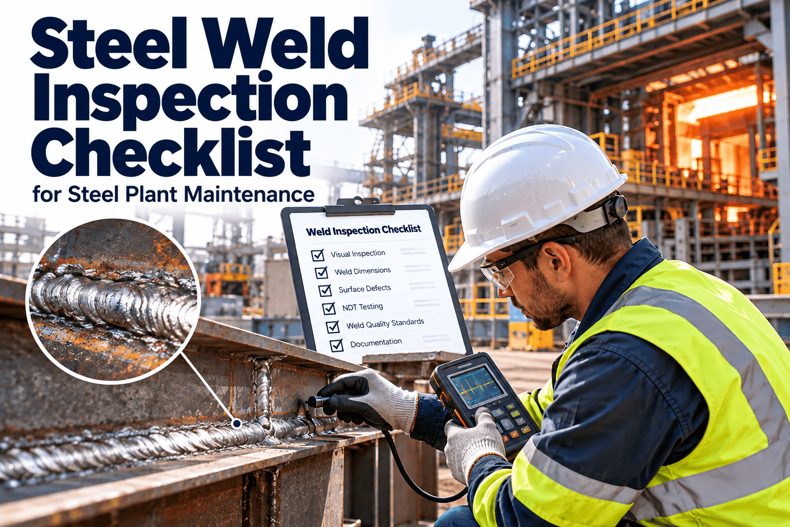
Steel plants run on welded equipment. Ladle shells, crane runway girders, conveyor structures, chutes, gas mains and mill stand components are repaired and modified by welding throughout their lives, often under shutdown pressure and by different crews each time. When a weld is inspected against a different standard by each inspector, recorded on paper and approved without evidence, defects slip through and repair history disappears. This steel weld inspection checklist standardises visual, dimensional and surface checks, repair status, evidence and approval, and shows how to run it as a digital workflow in Oxmaint steel plant CMMS.
Steel Weld Inspection Checklist for Steel Plant Maintenance
One standard way to inspect maintenance and repair welds across the plant: from joint preparation to visual and dimensional acceptance, defect disposition, repair tracking and signed approval with photo evidence.
Why Weld Inspection Needs Standardising in Steel Plants
Maintenance welding in a steel plant differs from shop fabrication. Work happens in place, under heat, dust and time pressure, on steels whose grade and service history are not always known, and it is inspected by whoever is available on that shift.
Inconsistent acceptance
One inspector accepts undercut that another would reject because no acceptance criterion or quality level was specified on the job.Lost repair history
The same crack on a crane girder or ladle trunnion area is repaired repeatedly, but nobody can see how many times or by which procedure.Evidence gaps
Sign-off sheets exist, but without photos, measurements or NDT reports there is nothing to show an auditor or an investigation team.Qualification not verified
Welders and procedures are assumed to be qualified for the joint rather than checked against the record before work starts.Welded Assets That Carry the Most Risk
Not every weld needs the same level of inspection. Weight the checklist by what happens if the weld fails in service.
| Asset | Typical weld work | Consequence of weld failure | Inspection emphasis |
|---|---|---|---|
| Ladles and ladle hooks area | Shell crack repair, trunnion area reinforcement, lug repairs | Molten metal release, dropped load | Visual plus surface NDT; engineering approval for load-bearing areas |
| Overhead crane girders and runways | Fatigue crack repair, rail clip and stiffener welds | Structural failure under lift, crane downtime | Crack detection at weld toes, repeat-location tracking |
| Conveyor structures and chutes | Liner plate welding, bracket repairs, wear plate hardfacing | Material spillage, belt damage, falling components | Visual and dimensional, attachment integrity |
| Rolling mill stands and components | Housing repairs, guide and chock repairs, roll hardfacing | Mill stoppage, product damage | Surface and volumetric NDT per OEM guidance |
| Gas mains and pressure parts | Pipe, flange and nozzle welds on process gas lines | Gas leak, fire and toxic exposure | Applicable pressure code, qualified procedures, NDT and pressure test |
| Furnace and vessel shells | Shell plate and cooling element welds | Breakout, water ingress, extended outage | Procedure control, preheat records, NDT where specified |
The Three-Stage Weld Inspection Checklist
Most weld defects are cheaper to prevent than to find. The checklist splits inspection into before, during and after welding so problems are caught at the stage where they start.
Before welding
- Welding procedure specification (WPS) identified and applicable to the base metal, thickness, position and process
- Welder qualification confirmed as current for the process and position, for example under ISO 9606 or the relevant AWS or ASME route
- Base metal identified; where the grade is unknown on older equipment, engineering guidance obtained before welding
- Joint preparation checked: bevel angle, root face, root gap and cleanliness free of rust, oil, paint and scale
- Fit-up and alignment checked with gauges, including misalignment on butt joints
- Crack removal on repairs confirmed complete, for example by surface NDT of the excavation
- Consumables match the WPS and are stored and dried as required
- Preheat method and temperature confirmed where the WPS requires it
- Permit to work, hot work controls and isolation in place
During welding
- Preheat and interpass temperatures measured and recorded
- Welding parameters kept within the WPS range for current, voltage and travel speed where monitored
- Root pass inspected before filling on critical joints
- Inter-run cleaning completed to remove slag and prevent inclusions
- Back gouging checked for sound metal on double-sided joints
- Distortion monitored and controlled on thin or long sections
- Shielding gas flow and wind protection checked for gas-shielded processes
After welding
- Hold time observed before final inspection where the WPS or code requires it for hydrogen-crack-susceptible steels
- Visual inspection of the full weld length against the specified acceptance criteria
- Dimensional checks of size, profile and reinforcement recorded
- Surface defects identified, measured and dispositioned
- Post-weld heat treatment records attached where required
- NDT performed where specified, by certified personnel, with reports attached
- Photos of the finished weld, with location reference, uploaded
- Area cleaned, coatings reinstated and asset released
Surface Defect Ledger: What to Look For
Imperfections are classified in ISO 6520-1, and acceptance limits come from the specified code or quality level, such as ISO 5817 levels B, C or D or the visual criteria in AWS D1.1. The ledger tells inspectors what each defect looks like and where it usually comes from.
Dimensional Checks and the Gauges That Prove Them
A weld that looks sound can still be undersized. Dimensional checks turn "looks fine" into a recorded number that can be compared with the drawing.
Choosing the Right NDT Method
Visual testing to ISO 17637 comes first on every weld. Other methods are added based on the defect type you need to find, the material and the criticality of the joint. NDT personnel should hold certification such as ISO 9712 or an employer scheme under SNT-TC-1A.
| Method | Finds | Works on | Limits in a steel plant |
|---|---|---|---|
| Visual testing (VT) | Surface imperfections, profile and size | All welds | Surface only; depends on access, lighting and inspector skill |
| Magnetic particle (MT) | Surface and near-surface cracks | Ferromagnetic steels only | Needs clean surface; not for austenitic stainless |
| Dye penetrant (PT) | Surface-breaking cracks and porosity | Most non-porous metals | Surface-breaking defects only; temperature-sensitive |
| Ultrasonic (UT, PAUT) | Internal lack of fusion, cracks, thickness | Most steels and thicknesses | Needs skilled operator and couplant; hot surfaces need special probes |
| Radiography (RT) | Porosity, slag, incomplete penetration | Butt welds with two-side access | Radiation safety exclusion zones; less suited to fillet welds |
Give Every Inspector the Same Weld Checklist
Build your three-stage weld inspection in Oxmaint, capture gauge readings and photos on mobile, and route rejected welds straight into repair work orders.
Repair Status: From Finding to Accepted Weld
A rejected weld is only closed when the repair has been re-inspected and approved. Tracking each weld through defined states prevents repairs from being signed off on the word of the person who made them.
What a Complete Weld Inspection Record Contains
Evidence is what makes an approval defensible. A standard record means any weld can be traced back months or years later.
- Asset and weld ID
- Equipment tag, weld number or map reference, and location on the asset
- Procedure and welder
- WPS reference, welder ID and qualification status at the time of welding
- Materials
- Base metal grade or assessment, consumable type and batch where tracked
- Measurements
- Preheat, interpass, weld size, reinforcement and undercut readings
- Visual results
- Pass or fail per item, with the acceptance standard or quality level stated
- Photo evidence
- Before, during and after photos, including any defect with a scale reference
- NDT reports
- Method, technician certification level, result and report attachment
- Approval
- Inspector sign-off, engineering approval where required, date and time
AI Quality Inspection and Computer Vision in Weld Checks
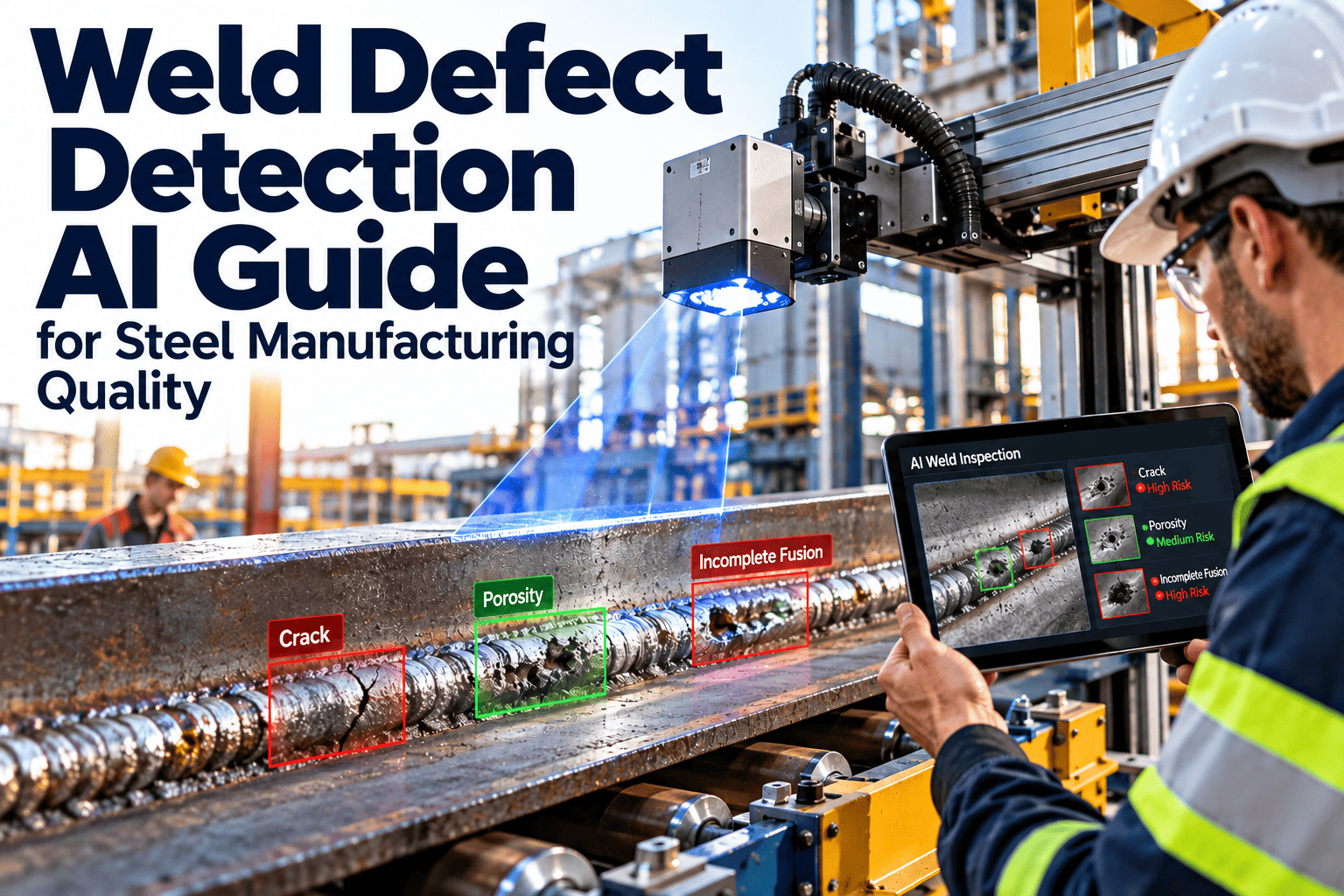
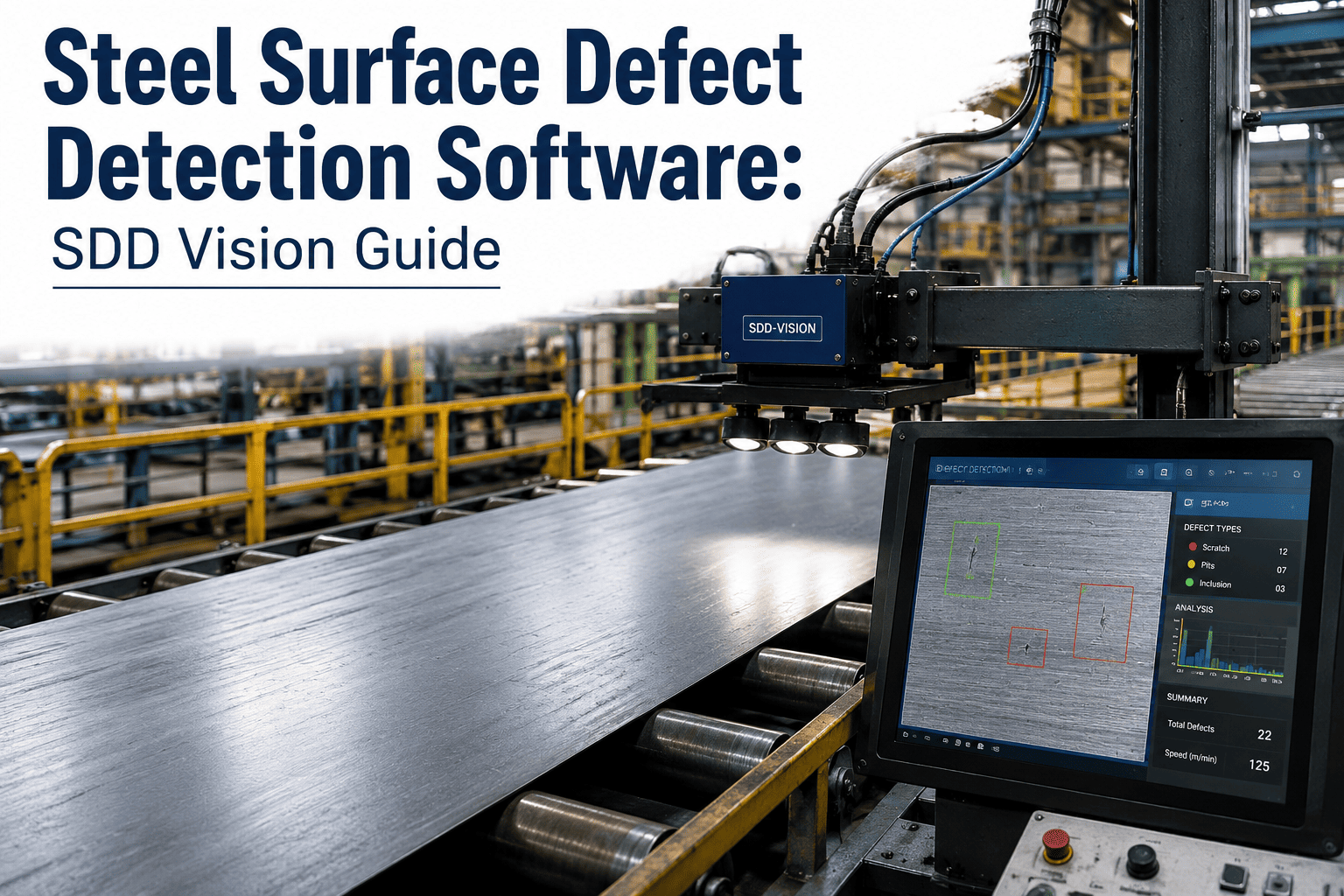
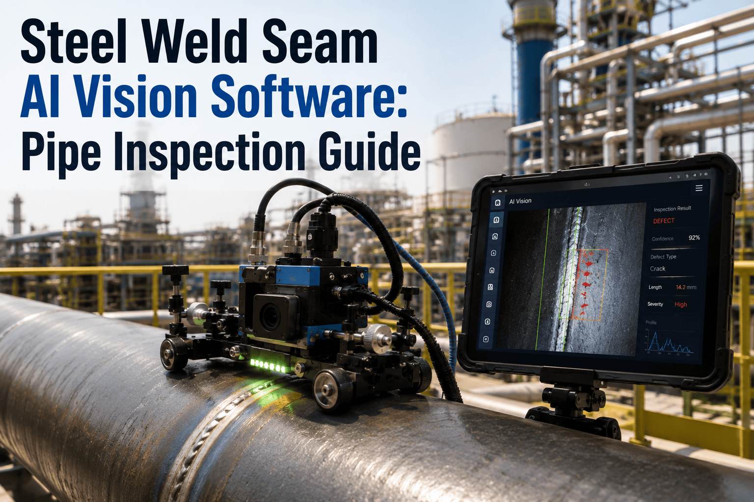
Computer vision is increasingly used to detect visible weld surface defects in images, especially in automated and robotic welding. For maintenance welding, it is best seen as a support to inspectors rather than a replacement.
Where AI inspection helps
- Flagging visible surface imperfections such as porosity, spatter and irregular bead profile in images
- Applying the same detection logic on every image, which reduces variation between inspectors
- Screening large numbers of photos so inspectors focus on flagged welds
- Building a searchable library of defect images over time
Where it has limits
- A camera only sees the surface; internal defects still need UT or RT
- Models need large, consistently labelled image sets to perform reliably
- Glare, scale, dust and access in a steel plant affect image quality
- Code acceptance still requires a qualified person to sign the result
Standardisation comes first
AI inspection depends on data that is consistent: the same defect names, the same photo angles, the same pass or fail criteria and a recorded outcome for every weld. A standardised digital checklist creates that foundation today, whether or not your plant adopts automated inspection later.Common Weld Inspection Mistakes to Avoid
These gaps appear repeatedly in maintenance welding and are easy to close once the checklist is standardised.
- Inspecting only the finished cap and never seeing the root, back gouge or crack excavation on critical repairs
- Signing off welds without stating which code or quality level the acceptance was judged against
- Carrying out final inspection immediately after welding on steels where delayed hydrogen cracking is a known risk
- Recording "OK" instead of the measured weld size, undercut depth or preheat temperature
- Taking photos with no location reference, so nobody can match the image to the weld later
- Closing a repair work order before the re-inspection result has been entered and approved
Weld Quality KPIs for Plant Maintenance
Track a small set of measures that show whether weld quality is improving and whether the inspection process is being followed.
Running the Weld Checklist in Oxmaint
Oxmaint is a maintenance management platform. It structures the inspection, keeps the evidence with the asset and connects findings to repair work.
Frequently Asked Questions
What should a steel weld inspection checklist include?
Checks before, during and after welding: procedure and welder qualification, fit-up, preheat, visual and dimensional acceptance, surface defects, NDT where required, repair status, photo evidence and signed approval.
Which standards set weld acceptance criteria?
Common references include ISO 5817 quality levels, AWS D1.1 for structural steel and ASME codes for pressure parts. The job should state which one applies before inspection starts.
Can AI replace a qualified weld inspector?
No. Computer vision can flag visible surface defects in images, but internal defects need NDT and code acceptance still needs a qualified person to sign off the result.
How do we track weld repairs on the same location?
Give each weld a location ID on the asset and record every inspection and repair against it. Oxmaint keeps this history on the asset so repeat repairs are visible.
How long does it take to set up a digital weld checklist?
It depends on how many templates and assets you start with. Many teams begin with one high-risk asset group and expand. Book a demo to plan your rollout.
Inspect, Repair and Approve Every Weld With Evidence
Replace paper sign-off sheets with a standard digital weld inspection that your inspectors, crews and engineers all follow. Start with your highest-risk assets in Oxmaint today.