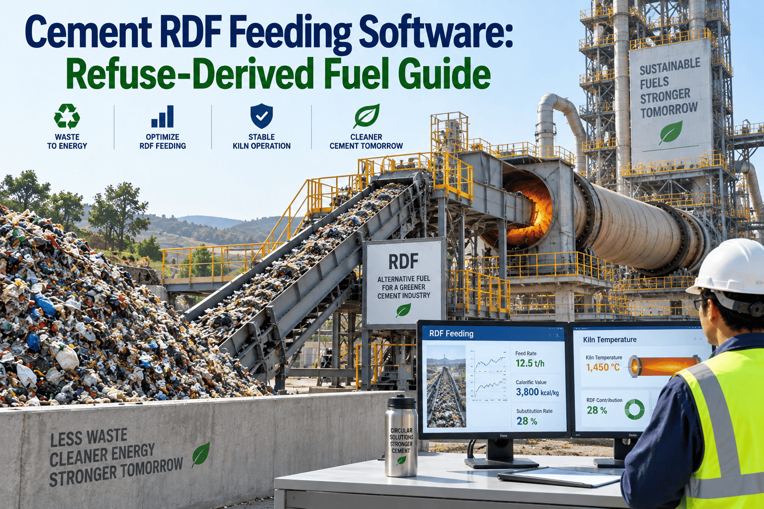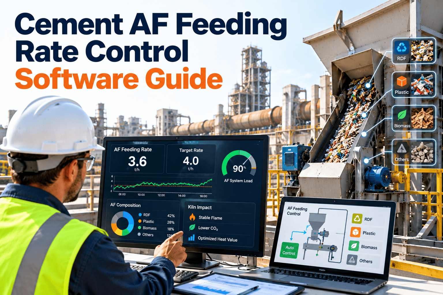
Stable alternative fuel (AF) feeding is as much a maintenance discipline as a process one. When the drop rate to the calciner or main burner swings, the kiln experiences it as shifting heat release, an unsteady flame and changing gas conditions. This guide explains where cement AF feeding rate variability really comes from, which equipment drives it and how plants manage it through inspection, calibration and work order discipline. See how a cement plant CMMS from Oxmaint keeps the whole feeding chain healthy.
Cement AF Feeding Rate Control: Stable Drop Rates at the Calciner and Main Burner
Rate swings wear refractory, unsettle the flame and raise build-up risk. Oxmaint gives maintenance teams the schedules, calibration records and work orders that keep every metering device on the AF line doing its job.
Erratic drop rate
Stable drop rate
Why the drop rate matters more than the daily average
A kiln does not respond to a daily average. It responds to what enters the calciner and main burner minute by minute. A plant can report a healthy thermal substitution rate (TSR) for a shift and still have fed fuel in surges and gaps.
1. The rate swings at the dosing point
Bridging in a bin, a worn screw or a drifting scale delivers fuel in pulses instead of a steady stream.
2. Heat release swings
RDF, biomass, shredded plastics and tyre chips vary in moisture, density and particle size. Uneven feeding turns that variability into uneven heat release.
3. Process conditions move
Operators react with changes to kiln feed, fuel and draft. Oxygen, CO and temperatures at the kiln inlet and preheater begin to oscillate, and build-up risk rises.
4. Refractory and quality pay
Repeated thermal cycling shortens lining life in the calciner and burning zone. The same swings can disturb clinker quality and emissions stability.
Many root causes in this chain are mechanical or instrumentation issues. That is why feed rate management belongs in the maintenance system as well as the control room.
Where AF feeding rate variability starts, asset by asset
Most plants chase the symptom on the operator screen. The table below traces common drop rate problems back to the equipment and the maintenance action that removes them.
| AF line asset | Typical problem | Effect on drop rate | Maintenance response |
|---|---|---|---|
| Storage bin and walking floor | Bridging, rat-holing, hydraulic leaks, worn push rails | Intermittent starvation then surge | Scheduled inspection, hydraulic checks, wear measurement |
| Metering screw or feeder | Flight wear, material wrapping, gearbox and motor issues | Lower delivery at the same speed | Wear limits, torque and amp trending, planned replacement |
| Weigh feeder and load cells | Calibration drift, build-up on the frame, damaged cells | Reported rate differs from real rate | Calibration schedule with records and tolerance limits |
| Rotary valve or airlock | Clearance wear, air leakage, jams from oversize pieces | Pulsing flow and false air | Clearance checks and seal replacement on condition |
| Pneumatic conveying line | Partial blockages, worn bends, blower performance loss | Slugging at the burner or calciner | Pressure trend review and bend thickness checks |
| Injection points | Build-up, burner tip damage, refractory erosion nearby | Poor dispersion and flame effects | Inspection during every planned stop |
| Shredder and screens upstream | Knife wear, screen blinding, foreign metal | Particle size drift that changes flow | Knife and screen condition checks and spares planning |
| Level and flow sensors | Dust coating, wiring faults, wrong settings | False signals to the control system | Inspection route and loop checks with sign-off |
Risk matrix: which AF line assets need the tightest PM
Not every device deserves the same attention. Rank assets by how strongly a failure disturbs the drop rate and how often it fails, then set preventive frequency from that ranking.
- Dark cells receive condition-based or short-interval preventive tasks.
- Medium cells follow a standard preventive calendar tied to run hours.
- Light cells are inspected on rounds and repaired when findings justify it.
Reactive feeding versus managed feeding
The difference is rarely a new machine. It is whether feeding equipment is treated as a controlled asset class with owners, limits and records.
Reactive AF feeding
- Scale calibration happens when someone doubts the reading
- Blockages are cleared and forgotten
- Operators compensate by hand and do not log why
- Spares for screws and valves are bought after failure
- Rate swings are blamed on fuel quality by default
- Refractory damage is investigated without feed history
Managed AF feeding
- Calibration runs on a schedule with tolerance and sign-off
- Every blockage becomes a coded event with a cause
- Operator observations flow into inspections and work orders
- Critical spares are stocked from criticality and wear history
- Fuel variability and equipment drift are separated in analysis
- Refractory reviews include feed events and downtime records
A six-step maintenance loop for feeding rate stability
This loop turns feed rate management into repeatable routines that any shift can follow.
Calibrate
Verify weigh feeders and belt scales against test weights or material checks, and record the as-found and as-left values.
Inspect
Walk the line from bin to injection point using a mobile checklist with photos for wear, leaks and build-up.
Detect
Review trends such as motor current, line pressure and feeder speed against delivered mass to spot drift early.
Dispatch
Raise a work order with priority from asset criticality, then assign it with the correct isolation steps.
Verify
Confirm the repair by checking rate stability after restart, not just that the machine runs.
Learn
Group repeat events by cause and feed the findings back into task lists, spares and operating limits.
Put your AF feeding line under maintenance control
Start with the bin, feeder, valve and injection point on one kiln line. Build the checklists, calibration tasks and work order flow, then extend to the rest of the plant.
Reading operator symptoms as maintenance clues
Control room observations are often the first sign of a feeding equipment problem. A shared vocabulary between operators and maintenance shortens the time from symptom to fix.
| What operators see | Mechanical possibilities to check first |
|---|---|
| Feeder speed rises but delivered mass falls | Screw flight wear, slipping coupling, material wrapping, scale drift |
| Rate oscillates on a regular cycle | Walking floor stroke pattern, rotary valve pocket filling, belt tracking |
| Line pressure climbs between cleanouts | Partial blockage, worn bends, blower filter or seal loss |
| Sudden rate drop with no alarm | Bridging above the feeder, tripped interlock, failed sensor signal |
| Flame or calciner temperature wanders | Injection point build-up, uneven dispersion, pulsing upstream |
Capture the symptom, the asset and the confirmed cause on every closed work order. After a few months, the pattern shows which assets and which fuels cause the most disturbance.
Trends shaping AF feeding in cement plants
Plants are raising thermal substitution targets and widening the fuel mix to include RDF, biomass, sewage sludge and tyre-derived fuel. Each new material brings its own handling behavior, and feeding systems must cope with more variability than they were first designed for.
What to record on every AF line work order
Good data turns individual repairs into learning. Keep the form short enough that technicians complete it in the field.
- Asset and location from bin to injection point
- Fuel type being fed when the problem occurred
- Symptom reported by the operator and the time it started
- Confirmed cause chosen from a short coded list
- Parts used, labor hours and downtime minutes
- Verification result after restart, including rate stability
Over time these fields support Pareto charts of repeat causes, which tell you whether to redesign a chute, change a valve spec or simply tighten the inspection interval.
KPIs that show whether AF feeding rate management is working
Pick a small set, define each one precisely and review it on a fixed rhythm. Targets should come from your own baseline.
| KPI | How to define it | Why it matters |
|---|---|---|
| Feed rate deviation | Spread of delivered rate around setpoint over a fixed interval | Shows stability directly rather than hiding it in an average |
| Time inside setpoint band | Share of running time within an agreed tolerance | Easy for operators and managers to track together |
| AF system availability | Run time divided by planned run time for the feeding chain | Links equipment health to TSR delivery |
| Blockage events | Count and duration per month by location and cause | Reveals repeat problems at bins, valves and lines |
| Calibration compliance | Completed calibrations against those scheduled | Protects confidence in the reported rate |
| Planned versus reactive work | Share of AF line labor hours that are planned | Indicates control of the asset class |
| Feed-related process events | CO excursions or kiln upsets linked to feed interruptions | Connects maintenance to process and refractory outcomes |
Safety, permits and records around AF handling
Alternative fuel areas combine moving equipment, dust, fire risk and regulatory scrutiny. Documentation needs to be as consistent as the feed itself.
Safety and permit controls
- Lockout and tagout steps stored with every feeder and screw job plan
- Permit-to-work for confined space entry into bins and silos
- Fire detection and suppression checks on RDF and biomass storage
- Dust control and housekeeping routes on the AF area
Records auditors and managers request
- Calibration certificates and as-found results per scale
- Inspection history with dates, findings and photos
- Work orders showing cause, fix and verification
- Training and competence records for AF line technicians
Requirements differ by country and permit, so confirm the applicable fire, explosion and emission rules for your site.
How Oxmaint supports cement plant AF feed rate management
Oxmaint is a maintenance management platform. It does not replace the control system that sets the feeder speed. It keeps the equipment behind that system reliable and documented.
Common mistakes in cement plant AF feed rate management
Weekly AF line checklist for supervisors
Use this as a starting template and adapt it to your feeding layout.
- Walk the line from receiving to injection point and log defects with photos
- Compare delivered mass against feeder speed for each metering device
- Check rotary valve and airlock noise, leakage and motor current
- Inspect pneumatic bends and flexible connections for wear
- Confirm fire detection and suppression devices are in service
- Review open work orders on A-critical AF assets and their age
- Record any operator manual overrides and the reason given
A 30-60-90 day rollout
Keep the first quarter small enough to finish and measurable enough to defend.
- Register AF line assets and rank criticality
- Load calibration and PM tasks
- Train technicians on mobile inspections
- Code blockage and rate events by cause
- Set wear limits for screws and valves
- Link critical spares to assets
- Review KPIs with operations and process
- Remove repeat causes through RCA
- Plan extension to a second feeding line
Frequently asked questions
What causes unstable AF feeding rates?
Fuel variability plus bridging, worn screws, valve leakage, scale drift and line blockages. Maintenance records help separate equipment causes from fuel causes.
Can a CMMS control the feeder?
No. It manages calibration, inspection and repair of the feeding equipment so the control system works with reliable data. Book a demo to see the workflow.
Which AF assets should we start with?
Start with weigh feeders, metering screws, rotary valves and injection points, because they influence delivered rate most directly.
How often should scales be calibrated?
Set the interval from vendor guidance, material behavior and your drift history, then tighten it where checks keep failing.
How do we start on one line?
Register the assets, load checklists and calibration tasks, and sign up to pilot the workflow on a single kiln line.
Stop managing rate swings and start preventing them
Give your team one place for AF line inspections, calibrations, work orders and spares, so stable drop rates become routine rather than luck.