Standard industrial sensors fail within months in cement kiln zones where ambient temperatures exceed 250°C and radiant exposure destroys standard cable insulation. Pyroprocessing environments demand a fundamentally different approach to instrumentation — one that accounts for thermal cycling, vibration, abrasive dust, and corrosive combustion gases simultaneously. This guide covers sensor selection criteria including temperature ratings, mounting methods, cable types, and CMMS communication protocols for reliable condition monitoring across all kiln zones. If your plant is still losing sensors to premature failure, start a free Oxmaint account to track sensor health and replacement cycles automatically, or book a 30-minute review with our cement plant specialists.
Cement Plant Engineering
High-Temperature Sensor Selection for Cement Kiln Zones
From preheater tower to cooler grate — choose sensors that survive 250°C+ ambient, abrasive dust, and continuous thermal cycling without unplanned downtime.
250°C+
Ambient temp in kiln zone
3–7×
Higher cost of reactive sensor failure
1,450°C
Clinker sintering zone peak
Kiln Zone Temperature Map
Each zone in the pyroprocessing circuit presents distinct sensor challenges. Matching sensor specification to zone conditions is the first step to avoiding premature failure.
80–350°C
Preheater Tower
Cyclone stages, raw meal feed. High dust loading, moderate temps. Type K thermocouples with stainless protection tubes work well.
850–1,000°C
Calciner
Fuel injection, 90% decarbonation. Requires high-alumina ceramic protection tubes. Infrared pyrometers preferred for non-contact measurement.
1,200–1,450°C
Burning Zone
Clinker sintering, maximum thermal stress. Only infrared scanners and platinum-rhodium thermocouples survive. Refractory-mounted designs mandatory.
200–800°C
Transition / Cooling
Clinker discharge, cooler grate. Rapid thermal cycling. Armored MI cable thermocouples with replaceable heads reduce maintenance downtime significantly.
Sensor Type Selection Matrix
Use this matrix to match measurement technology to kiln zone conditions. Wrong sensor type is the single largest cause of premature failure in cement plants.
| Sensor Type |
Max Temp Rating |
Best Kiln Zone |
Key Advantage |
Main Limitation |
| Type K Thermocouple |
1,260°C |
Preheater, Cooler |
Low cost, wide availability |
Drift above 800°C, oxidation |
| Type B / Type S (Pt-Rh) |
1,700°C |
Burning Zone |
Stable at extreme temps |
High cost, fragile element |
| Infrared Pyrometer |
3,000°C (non-contact) |
Calciner, Burning Zone |
No contact, instant response |
Dust and flame interference |
| Kiln Shell Scanner |
Surface to 400°C |
Kiln shell exterior |
Full shell thermal map |
External only, not internal |
| MI Cable RTD |
600°C |
Preheater, Transition |
High accuracy, stable |
Slower response, cost |
| Fiber Optic DTS |
300°C (cable) / 700°C (probe) |
Preheater stages |
Distributed measurement |
Complex installation |
Cable and Wiring Selection for High-Temperature Zones
Cable failure accounts for over 40% of sensor system outages in cement kilns. The extension cable must match the thermocouple type exactly and withstand both ambient heat and radiant exposure from the kiln shell.
Mineral Insulated (MI) Cable
Up to 1,100°C continuous
Stainless or Inconel outer sheath packed with magnesium oxide insulation. The only cable that survives direct kiln zone exposure without conduit. Mandatory for burning zone and calciner applications.
Fibreglass-Insulated Extension
Up to 450°C
Braided fibreglass over thermocouple alloy conductors. Suitable for preheater tower and transition zone runs where cables are in conduit and shielded from direct radiant heat.
PTFE / Silicone Extension
Up to 260°C
Standard industrial grade. Acceptable only in control room runs, terminal head connections, and locations fully isolated from kiln zone ambient temperatures.
Armored Thermocouple Cable
Up to 650°C (sheath dependent)
Flexible interlocked stainless armor over MI core. Preferred where cables must route through mechanical equipment areas with vibration, abrasion risk, or frequent maintenance access.
Mounting Methods and Protection Strategies
Even a correctly specified sensor will fail early if mounted without accounting for thermal expansion, vibration, and access requirements for replacement.
01
Use ceramic protection tubes in calciner and preheater zones
High-alumina (99%+ Al₂O₃) tubes resist chemical attack from SO₂, alkali vapors, and chlorides present in calciner atmospheres. Replace protection tube rather than the thermocouple itself when signs of chemical attack appear.
02
Allow for thermal expansion in all rigid installations
Cement kiln components expand significantly at operating temperature. Install sensors with spring-loaded compression fittings or expansion joints to prevent mechanical stress cracking of ceramic elements during heat-up cycles.
03
Position infrared pyrometers to avoid flame and dust interference
Purge pyrometer sighting tubes continuously with clean instrument air at minimum 0.5 bar. Aim 15–20° off the flame centreline in the burning zone to avoid reading the luminous flame rather than the material bed temperature.
04
Mount vibration sensors on water-cooled housings for mill drives
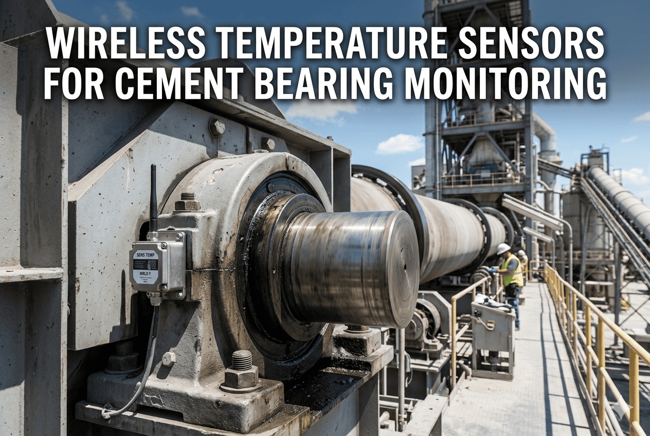
High-temperature accelerometers rated for 120°C–150°C are suitable for most cement mill bearing locations. Water-cooled sensor mounts are required only for sensors positioned within 2 meters of the kiln shell or direct flame radiation zones.
05
Plan replacement access routes before commissioning
Sensors in burning zone and calciner must be replaceable during short maintenance windows. Design sensor installations so the element can be withdrawn and replaced without dismantling refractory or major structural components.
Key Performance Indicators: Sensor Reliability in Cement Plants
These KPIs help maintenance teams track sensor system health and justify investment in higher-specification instrumentation.
Mean Sensor Life
Target: 12–18 months (burning zone)
Best performers achieve 14+ months average life on kiln zone thermocouples through correct specification and protection tube replacement programs.
Calibration Drift Rate
Acceptable: <5°C/year for Type K
High drift indicates chemical attack or mechanical stress. Trending drift in your CMMS gives early warning before outright sensor failure occurs.
Sensor-Related Downtime
Industry avg: 1.8% of kiln runtime
Top-quartile plants reduce sensor-caused stoppages to under 0.5% by combining planned replacement schedules with predictive monitoring.
Planned vs. Reactive Replacements
Target: >70% planned
Reactive replacements during kiln operation cost 4–6x more than planned replacements during scheduled maintenance windows due to access difficulty and hot-work procedures.
Integrating Sensor Data with Your CMMS
Raw sensor readings become predictive maintenance intelligence only when connected to a CMMS that tracks installation dates, calibration history, and alert thresholds by asset.
Digital input protocols
Modern cement plant sensors support HART, FOUNDATION Fieldbus, or Profibus PA communication alongside 4–20mA analog. Configure your CMMS to receive both process values and diagnostic data — HART-enabled transmitters report self-diagnostic alerts that predict failure 2–4 weeks early.
Calibration schedule automation
Set CMMS work order triggers based on sensor operating hours, not calendar intervals. A kiln zone thermocouple accumulating 700 hours per month needs calibration checks at 4,000-hour intervals — calendar-based scheduling misses this entirely when kilns run continuously.
Failure mode tagging
When replacing sensors, record failure mode in the CMMS: chemical attack, mechanical fracture, cable burn, connector corrosion. Analyzing failure mode distribution across 12 months reveals the primary failure driver so you address the root cause, not just the symptom.
Spare parts integration
Link sensor asset records to spare parts inventory. The CMMS should automatically reserve replacement thermocouples and protection tubes when a sensor enters a degraded state — eliminating the 2–5 day wait for emergency parts that extends kiln downtime unnecessarily.
Automate your sensor maintenance tracking. Oxmaint connects sensor asset records, calibration schedules, spare parts inventory, and work orders in one platform — built for cement plant maintenance teams.
Real-World Example: Reducing Thermocouple Failures by 62%
A 3,500 tpd clinker plant in Southeast Asia was replacing burning zone thermocouples every 2–3 months at a total annual cost of $180,000 including parts, labor, and associated kiln stoppages. After a sensor audit, three root causes were identified: wrong thermocouple type (Type K instead of Type S), standard PVC extension cables melting in the cable tray adjacent to the kiln shell, and no spring-loaded compression fittings allowing thermal expansion fractures.
After switching to Type S Pt-Rh thermocouples with 99% alumina protection tubes, replacing cable runs with MI cable, and installing expansion compensation fittings, average thermocouple life extended from 2.5 months to 16 months. Annual sensor-related costs dropped to $68,000 — a 62% reduction — and unplanned kiln stoppages attributed to sensor failure fell from 14 per year to 3.
Book a demo to discuss a sensor audit for your cement plant
Frequently Asked Questions
What thermocouple type is best for cement kiln burning zone?
Type B (Pt-30%Rh / Pt-6%Rh) or Type S (Pt-10%Rh / Pt) are the correct choices for burning zone temperatures of 1,200–1,450°C. Type K is not suitable above 1,100°C and drifts significantly above 800°C. Use 99%+ alumina protection tubes and MI cable extensions.
Track your sensor specifications in Oxmaint to ensure the right type is always installed.
Can standard vibration sensors be used on cement mill bearings?
Yes, if the bearing housing temperature stays below 85°C — which is typical for most cement ball mill and VRM main bearings. For bearings near the kiln or in high-ambient locations, specify sensors rated to 120°C or 150°C. Always check the sensor's maximum operating temperature against the actual bearing housing temperature during operation, not just at ambient.
Book a review to audit your current sensor specifications.
How often should kiln zone thermocouples be calibrated?
Calibration intervals depend on zone and thermocouple type. Burning zone Type S/B sensors should be checked every 4,000–6,000 operating hours. Preheater zone Type K sensors every 8,000 hours. Any sensor showing drift greater than 5°C compared to a reference should be replaced or recalibrated immediately regardless of hours elapsed.
What causes infrared pyrometer readings to be unstable in the burning zone?
Three main causes: inadequate purge air flow allowing dust buildup on the sighting window, measuring through the luminous flame rather than beside it, and dirty or damaged sighting tubes. Maintain purge air at 0.5–1.0 bar continuously, aim the pyrometer 15–20° off-flame centerline, and clean sighting tubes weekly during kiln operation to maintain stable readings.
How does a CMMS help with cement plant sensor management?
A CMMS like Oxmaint tracks sensor installation dates, failure mode history, calibration records, and links sensors to spare parts inventory. This enables predictive replacement scheduling, failure root cause analysis, and automatic spare parts reservation — reducing reactive replacements that cost 4–6x more than planned ones.
Sign up free to see how it works for your plant.
Stop Losing Sensors to Preventable Failures
Oxmaint helps cement plant maintenance teams track sensor specifications, calibration schedules, failure modes, and spare parts — so every sensor replacement is planned, not reactive.