The water-cooled bearing housing is the single most under-instrumented critical asset in the entire cement plant. It supports a 600-tonne rotating kiln operating at 1,450°C, runs on a hydrodynamic oil film no thicker than 0.02 mm, and depends on a continuous flow of cooling water through the cast-iron spherical seat to keep that film alive. Lose the water flow for ten minutes and the oil viscosity drops past the bearing's protective threshold; lose it for thirty and the bronze liner begins to seize against the supporting roller shaft. Most plants still monitor this critical loop with a single mechanical flow indicator on the discharge line that nobody looks at between weekly rounds — and a single missed reading turns into a $200,000-per-hour kiln stoppage and a six-figure bearing rebuild. The plants that have eliminated this failure mode share one practice: they connect every cooling-water flow meter, outlet temperature probe, and bearing temperature RTD to a maintenance system that does the watching for them, with Oxmaint's CMMS platform turning the cooling loop from an unwatched utility line into an alert-driven, work-order-generating asset record.
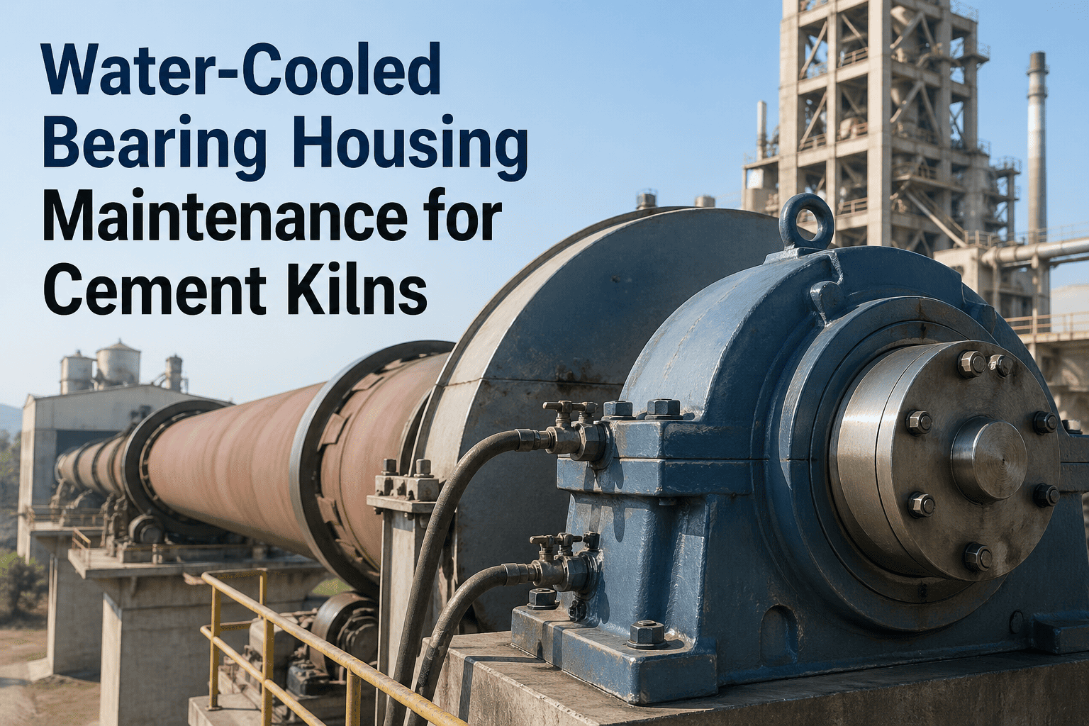
Water-Cooled Bearing Housing Maintenance for Cement Kilns
IoT flow monitoring, outlet temperature sensing, and CMMS-integrated work order generation across kiln support roller and trunnion bearing assemblies.
Anatomy of the Cooling Loop — What Actually Sits Inside the Bearing Housing
The water-cooled trunnion bearing housing is not a simple block with a cooling jacket. It is a precision-engineered assembly where every component is calibrated against thermal expansion, oil viscosity, and the 60–90 tonnes of axial force the kiln transmits through each supporting roller. Understanding what is inside the housing is the difference between catching cooling degradation early and discovering it after a bearing seize.
Cast-Iron Ball Socket with Internal Water Chambers
The spherical pad sits on the bedplate at a 30° angle to horizontal. Cooling water circulates through internal chambers cast directly into the iron — this is the actual cooling surface. Scale buildup or sediment in these chambers reduces heat transfer drastically without any external flow change.
Bronze Bearing Liner with Fixed Thrust Collar
The bronze liner rests on the ball socket and supports the support roller journal directly. Liner-to-shaft contact area must hold a continuous 30 mm strip along the full bearing length. A 0.003 × shaft diameter clearance is required for oil entry; below that, lubrication fails and the bearing heats up.
Hydrodynamic Oil Film
At rotation, oil is drawn into the wedge between shaft and liner forming a film 0.01 to 0.02 mm thick that completely lifts the journal off the liner. Film stability depends entirely on oil viscosity — and viscosity depends entirely on cooling water removing frictional heat.
Cooling Water Flow Indicator (Discharge)
OEM design places a mechanical flow indicator on the discharge branch — the only built-in cooling status check on most installations. This is the single point of failure: if nobody is watching it, the bearing has no cooling protection in the operator's data stream at all.
Thermal Sensor (Bearing Liner) & Oil Sight Glass
Thermal sensor suspended in the bearing liner gives oil pool temperature. Sight glass shows oil level and contamination state — water emulsification (mixing with cooling leak) is visible as cloudy oil. Both readings need to live inside the CMMS asset record, not on a paper logbook.
The Failure Cascade — How a Cooling Loss Becomes a Kiln Stoppage
Water cooling failures rarely announce themselves with a single dramatic alarm. They progress through five recognisable stages, each with a specific signature and a specific intervention window. Reading the cascade is the difference between a 2-hour controlled stop and a 5-day emergency rebuild. Book a demo to see how Oxmaint maps each stage to an automatic work order trigger.
Cooling Flow Drop
Flow rate falls below baseline. Could be valve drift, scale buildup in chambers, pump degradation, or supply header pressure loss.
Outlet Water Temperature Climb
Water outlet temperature rises 5–10°C above inlet differential baseline. Heat is no longer being carried away at the design rate.
Oil Pool Temperature Rise
Oil temperature climbs through the warning threshold. Viscosity drops sharply with each degree above 65°C — the protective margin starts collapsing.
Oil Film Thinning & Metal Contact
Hydrodynamic film drops below 0.01 mm. Intermittent metal-to-metal contact begins. Bearing temperature climbs through alarm threshold.
Bearing Seizure & Liner Damage
Bronze liner welds to journal. Permanent damage to liner surface and possibly to roller shaft. Recovery requires bearing rebuild and shaft inspection.
The Sensor Stack — Five Measurements That Make Cooling Failures Visible
One sensor is never enough. Each measurement covers a different stage of the failure cascade, and only the combined set gives a maintenance team the lead time to act before damage occurs. The five-sensor stack below is what differentiates plants that have eliminated cooling-driven kiln stops from plants that still treat them as unavoidable.
Inline magnetic or ultrasonic flow meter on the discharge branch. Catches Stage 1 flow drop before any temperature changes. The earliest signal in the entire cascade.
Two RTDs measuring supply and discharge water temperature. Differential ΔT trend is the most sensitive indicator of cooling chamber fouling — long before flow meter shows reduction.
RTD embedded in the bronze bearing liner reading oil pool temperature. Normal 40–65°C. Warning threshold 70°C. Alarm threshold 80°C. The single most-watched reading in the kiln control room.
Inline sensor measuring oil moisture content. Detects water emulsification from cooling-loop leaks before visible oil cloudiness appears in the sight glass. Critical for catching slow internal leaks.
Pressure transmitter on the supply header. Catches upstream pump failure, valve closure, or distribution header issues that affect multiple bearings simultaneously across the kiln.
Stop Discovering Cooling Failures After the Bearing Seizes
Oxmaint connects every flow meter, temperature probe, and oil sensor on your kiln support bearings to one CMMS — turning cooling loop data into work orders before a $200K-per-hour stoppage becomes the first warning.
Threshold Map — From Sensor Reading to CMMS Action
Continuous data without thresholds is just noise. The map below shows how each sensor reading translates directly into a maintenance response inside Oxmaint — no manual triage, no judgement calls, no "let's wait and see" decisions in the control room. Each threshold breach generates an asset-linked work order with the right parts, the right technician, and the right urgency.
| Sensor | Normal | Advisory | Alarm | CMMS Response |
|---|---|---|---|---|
| Bearing liner temp | 40–65°C | 65–70°C | > 80°C | Auto WO: oil sample + cooling check |
| Cooling water flow | 100% baseline | 80–95% | < 80% | Auto WO: chamber descale + flow path |
| Water ΔT outlet–inlet | Baseline ±2°C | +3 to +5°C | > +5°C | Auto WO: cooling chamber inspection |
| Inlet water pressure | OEM spec | −10% to −20% | < 80% spec | Auto WO: supply pump + header check |
| Oil moisture content | < 100 ppm | 100–200 ppm | > 200 ppm | Auto WO: leak test + oil change |
| Oil viscosity (sample) | OEM grade | −10 to −20% | > −20% | Auto WO: oil replacement scheduled |
Live Cooling Loop Dashboard — What Sensor-to-CMMS Looks Like
The condition feed below is what closed-loop bearing cooling monitoring looks like when the sensor stack flows directly into a maintenance system. Each row is a real signature mapped to an automatic CMMS action. No watching dials, no manual escalation chain, no waiting for the morning round to discover a problem that started six hours ago.
The Five Failure Modes That Account for 90% of Cooling Issues
Calcium and silica scale build inside the cast-iron water chambers. Heat transfer drops gradually — flow rate appears normal but ΔT keeps climbing. Quarterly chemical descale is the only effective preventive action.
Cooling water seeps into the oil reservoir through corroded internal pipework. Oil emulsifies, viscosity collapses, lubrication fails. Sight glass shows cloudy oil — but only if someone is looking. Oil moisture sensor catches it weeks earlier.
Cooling pump degradation, header pressure loss, or upstream valve drift. Affects multiple bearings simultaneously across the kiln — distinctive pattern of system-wide flow drop rather than single-bearing issue.
Mechanical paddle-wheel flow indicator stuck or jammed. Reading appears normal but actual flow has stopped. Discovered only after the bearing has overheated. IoT flow meters eliminate this entirely.
Suspended solids, bacterial growth, or pH excursions degrade heat transfer and corrode internal pipework. Often traces to upstream cooling tower problems rather than the bearing itself.
Auxiliary oil-to-water heat exchanger fouling on the oil-cooling circuit. Reduces oil cooling capacity even when cooling water flow is normal. Differential pressure across the exchanger is the early indicator.
The Maintenance Calendar — What Disciplined Plants Actually Do
Bearing Temperature Trend Review
Operators review 24-hour temperature trend per bearing in the CMMS dashboard. Slow upward drift catches scale buildup weeks before alarm threshold.
Cooling Flow & ΔT Verification
Verify flow rate and water differential temperature against rolling baseline. Flag any bearing where ΔT has shifted more than 2°C in the prior week — the earliest scale signature.
Oil Sample & Moisture Analysis
Lab oil sample logged against bearing asset record. Iron particles, viscosity, and water content trended over the bearing lifetime. Threshold breach auto-triggers oil replacement WO.
Cooling Chamber Chemical Descale
Circulate descale chemical through the spherical pad chambers during planned slowdown. Removes scale before heat-transfer degradation becomes severe enough to affect operation.
Bearing Liner Contact Pattern Inspection
During scheduled outage, inspect bronze liner contact strip. Continuous 30 mm strip indicates healthy operation; uneven or interrupted pattern signals shaft skew or thermal distortion.
Cooling Loop Pressure Test
Hydrostatic test of the internal cooling pipework to detect early-stage leaks before they emulsify the oil charge. Catches the most damaging slow-failure mode in the entire cooling system.
The ROI Math — Why Cooling Sensor Integration Pays Back in One Prevented Failure
The numbers on bearing cooling monitoring are not marginal. A single prevented seizure event covers the full sensor and CMMS investment with significant margin to spare. The cost stack below shows what cement plants actually spend when cooling failures progress through each stage of the cascade.
What Sensor-to-CMMS Integration Has Actually Delivered
The benchmarks below are typical results from cement plants that moved from periodic manual rounds to continuous sensor-to-CMMS monitoring on water-cooled bearing housings. The pattern is clear — the cost of one prevented seizure pays for the entire monitoring system many times over.
Frequently Asked Questions
The Bearing That Seizes Tomorrow Is the One Whose Cooling Loop Nobody Watched Today
Plants that have eliminated cooling-driven kiln stops did not buy more sensors — they connected the sensors they already had to a CMMS that watches every reading, every trend, and every threshold around the clock.