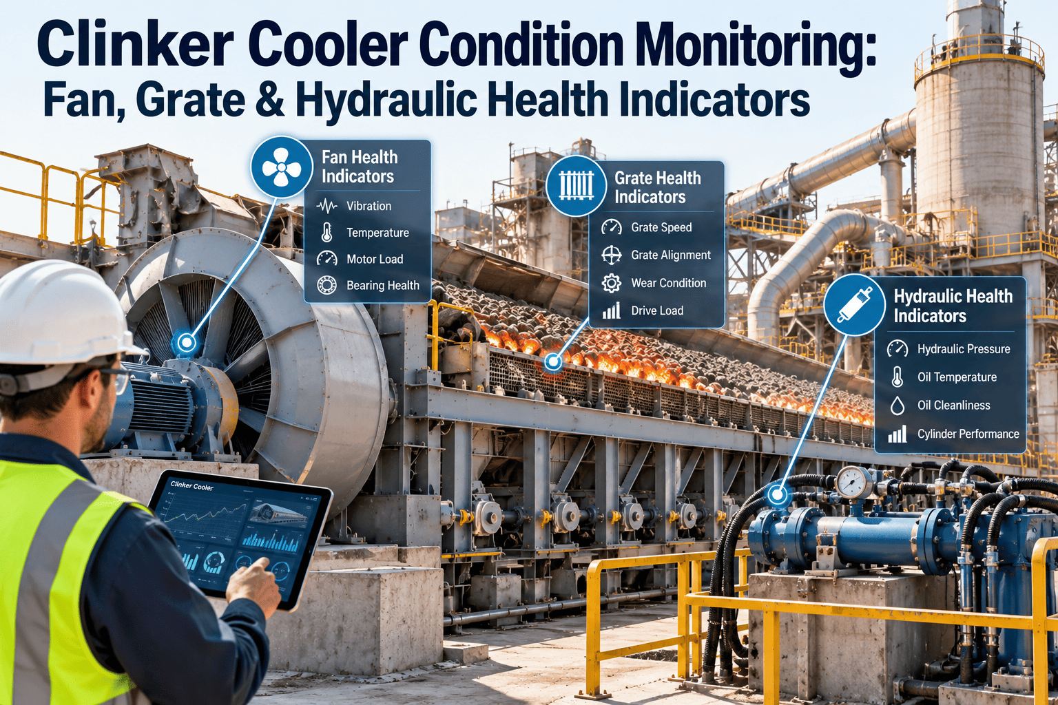
A clinker cooler rarely fails without warning. The fan that slowly loses airflow, the grate drive that starts to stutter and the hydraulic unit that runs a little warmer each week all send signals long before a kiln stop. The difficulty is that those signals sit in different places: the control room history, a vibration route and a technician's notebook. This guide explains which fan, grate and hydraulic indicators matter most, and how OxMaint maintenance management software turns them into planned work.
Clinker Cooler Condition Monitoring: Fan, Grate and Hydraulic Health Indicators
Track the indicators that show a cooler is drifting toward failure, set clear watch and act limits, and convert every warning into an owned work order before the kiln feels it.
- Undergrate pressure per compartment
- Motor current against damper position
- Bearing vibration and temperature
- Plate wear and warping
- Siftings and fall-through volume
- Bed behaviour and outlet temperature
- Working pressure and stroke time
- Oil temperature and filter pressure drop
- Oil cleanliness and leak points
Why Cooler Problems Stay Hidden Until the Kiln Feels Them
The cooler sits at the end of the burning line, so its faults travel upstream. Poor undergrate airflow leaves hot clinker on the grate, raises clinker outlet temperature, weakens secondary and tertiary air recovery and pushes fuel consumption up. Operations compensates first, and maintenance often hears about the mechanical cause late.
- Fans are inspected after a trip or a noise complaint
- Hydraulic oil is changed by calendar only
- Grate plate wear is discovered during the next shutdown
- Readings stay in the control room history
- Work is requested by phone and forgotten by the next shift
- Fan current and vibration are trended against damper position
- Oil temperature and filter pressure drop trigger inspection
- Siftings and plate condition are logged on every round
- Readings are compared with a baseline for each asset
- Every alert becomes a work order with an owner and a due date
Cooler Anatomy: Where Each Health Indicator Comes From
In a reciprocating grate cooler, three systems decide availability: the cooling air fans, the moving and fixed grate rows, and the hydraulic drive that moves them. Everything downstream, from the clinker breaker to the conveyor, depends on how well they perform.
Cooling Fan Health Indicators That Deserve a Baseline
Cooling fans work in dusty, warm conditions, and each compartment has its own air demand. A single fan reading means little; the pattern across compartments, dampers and motor current tells the story.
| Indicator | What It Reveals | Typical Cause | Maintenance Response |
|---|---|---|---|
| Undergrate pressure per compartment | Resistance of the bed and grate to airflow | Fine clinker, blocked aeration slots, worn seals | Inspect plates and seals in that compartment |
| Motor current against damper position | Whether delivered airflow matches the demand | Impeller wear, build-up, duct leakage, linkage slip | Check damper travel, impeller and inlet ducting |
| Bearing vibration | Imbalance, looseness and early bearing damage | Dust on blades, loose base bolts, poor lubrication | Balance, tighten, relubricate, plan a bearing check |
| Bearing temperature | Lubrication condition and load | Over or under greasing, misalignment | Verify the grease routine and alignment |
| Damper and drive response | Integrity of the airflow control loop | Actuator wear, loose linkage, drive faults | Calibrate, repair and record the as-found state |
Grate Health Indicators: From Early Sign to Act Now
Grate plates face abrasion, thermal cycling and mechanical load. Wear changes aeration geometry, so poor air distribution can appear long before a plate breaks. Typical consequences include red river streaks, snowman build-up in the hot zone and heavy siftings.
Hydraulic Health Indicators for the Grate Drive
The hydraulic power pack moves every grate row, so contamination or heat problems quickly become availability problems. Oil cleanliness is normally reported to ISO 4406, and target codes should follow the component manufacturer's guidance.
| Indicator | Healthy Pattern | Warning Pattern | Typical Action |
|---|---|---|---|
| Working pressure | Stable and repeatable at each stroke | Slow pressure build or drop under load | Check pump, relief valve and accumulator pre-charge |
| Oil temperature | Steady relative to ambient and load | Rising trend at the same load | Clean the cooler and check for internal leakage |
| Filter differential pressure | Gradual rise across the service interval | Rapid rise between changes | Find the contamination source, then change the element |
| Oil cleanliness and water | Within the manufacturer's target code | Particle or water content climbing | Sample, filter and correct breather or seal ingress |
| Cylinder stroke and drift | Consistent stroke time, no drift at rest | Slower stroke or drift when stopped | Inspect cylinder seals and valve leakage |
| Oil level and leak points | Stable level, dry fittings | Falling level, wet hoses or rod seals | Repair leaks and record top-up volumes |
Give Every Cooler Indicator an Owner and a Due Date
From Indicator to Closed Work Order
Monitoring only pays off when a warning ends in a repair. A simple five-step loop keeps condition data connected to maintenance action.
Define the baseline
Set watch and act limits
Capture readings
Trigger the work
Verify and learn
Reading Combined Symptoms Across Fan, Grate and Hydraulics
Most cooler faults show up as a combination. Comparing indicators side by side points maintenance to the right system on the first visit.
| Combined Pattern | Likely System | First Check |
|---|---|---|
| Outlet temperature rising while undergrate pressure is unchanged | Grate and bed distribution | Look for red river streaks and worn plates |
| Fan current up while undergrate pressure is down | Fan or ducting | Inspect impeller, damper and duct leakage |
| Slow grate stroke with rising oil temperature | Hydraulic drive | Check filter pressure drop, pump and relief valve |
| Siftings increasing across several shifts | Grate plates and seals | Schedule plate and seal inspection |
| One fan vibrating more after a cleaning | Impeller balance | Check for lost balance weights or uneven build-up |
Cooler KPIs Worth Reviewing Every Month
Cooler Round Checklist for Technicians
Fans
- Record motor current and damper position
- Note vibration, noise and bearing temperature
- Check inlet ducts and access doors for leaks
- Photograph visible impeller build-up
Grate
- Review camera or window view of bed shape
- Log siftings hopper and conveyor condition
- Flag warped, missing or cracked plates
- Compare outlet temperature with baseline
Hydraulics
- Read pressure, oil level and oil temperature
- Check filter indicators and breather condition
- Look for wet hoses, fittings and rod seals
- Note any slow or uneven grate stroke
Setting Baselines and Limits Without Guesswork
A limit only means something when it is compared with how that specific asset behaves when healthy. Cooler fans, grate drives and hydraulic units vary with kiln load, clinker size, ambient temperature and compartment layout, so copying generic numbers rarely works. Start with the manufacturer's guidance, then adjust using real operating history.
- Undergrate pressure and damper position for each compartment at stable kiln output
- Fan motor current, bearing temperature and vibration after a successful repair or balance
- Hydraulic working pressure, stroke time and oil temperature after an oil and filter change
- Clinker outlet temperature at a typical production rate
- Photos of plates, seals and the bed profile in good condition
- After a fan impeller replacement or major rebalance
- After grate plates or seals are changed in a compartment
- After a hydraulic pump, valve block or cylinder is replaced
- After a change in kiln fuel mix or clinker grindability that alters the bed
- After sensor replacement or recalibration
Typical Cooler Failure Scenarios and the Planned Response
The scenarios below show how the three indicator groups work together. They are illustrative patterns, not a substitute for the original equipment manufacturer's instructions.
Fan impeller build-up
Progressive grate plate wear
Hydraulic contamination
Slow grate stroke at high oil temperature
Red river with normal fan data
Where OxMaint Fits in a Cooler Monitoring Program
Condition monitoring produces information. A maintenance management system makes sure that information leads to a task, a crew, a spare part and a recorded result. These capabilities matter most for clinker coolers.
Planning Cooler Work Around Kiln Stops
Cooler repairs compete with other jobs for a limited stop window. Condition indicators help decide which work genuinely needs the next shutdown and which can wait. Without them, planners either overload the stop or leave a known problem to become an emergency.
Rank the work
- List all open cooler alerts and findings
- Sort by indicator severity and consequence
- Separate jobs needing a full stop from quick outages
- Agree the final list with operations
Prepare the resources
- Confirm plates, seals and bearings are in stock
- Book cranes, access and cooling time
- Assign crews and permits in each work order
- Attach drawings and previous findings
Close the loop
- Record as-found and as-left condition
- Capture new baseline readings after restart
- Log parts used and time spent
- Review results at the next reliability meeting
Challenges That Slow Cooler Monitoring Programs
Most plants already measure something on the cooler. The challenge is turning scattered measurements into consistent decisions.
- Too many alarms, so genuine warnings get ignored
- Readings taken in different units or at different times
- No clear owner for cooler health between operations and maintenance
- Findings written in handover notes that nobody searches
- Hydraulic oil analysis results filed away from the asset
- Keep a short list of indicators and review it regularly
- Standardise inspection checklists and units
- Name one reliability owner for the cooler
- Store findings, photos and results against the asset
- Link oil analysis outcomes to filter and oil change tasks