Clinker Cooler Daily Grate Plate Walk and Hot Air Loss Checklist
By Johnson on May 26, 2026
The clinker cooler is the one piece of equipment that controls secondary air temperature to your kiln, tertiary air to your calciner, clinker discharge temperature, waste heat recovery output, and grindability — all at the same time. A missed grate plate failure, a fan running at elevated amperage, or a red-river forming undetected can force a kiln shutdown within hours and cost $18,000 to $45,000 per hour in lost clinker production. The daily grate plate walk and hot air loss check is the one operator routine that catches all of these before the shift ends. Start logging your daily cooler readings in OxMaint free — mobile-ready checklists, fan amp trending, grate wear records, and auto-generated work orders in one platform configured for cement plants. Book a demo with an OxMaint cement specialist to walk through your cooler zone by zone.
Cement Plant Checklist · Daily Operator Walk · Clinker Cooler
Clinker Cooler Daily Grate Walk & Hot Air Loss Checklist
Grate wear observation, undergrate pressure, fan amperage, hot air loss indicators, hydraulic drive health, and CMMS sign-off — every reading your shift operator needs to log before handing over the keys.
Zone 1 — Hot End
900–1,100°C inlet
Highest wear rate
›
Zone 2 — Mid Cooler
400–700°C range
Heat recovery zone
›
Zone 3 — Cold End
65°C + ambient target
WHR & discharge
$18K–$45K
Per hour of unplanned kiln shutdown caused by cooler failure
76–86%
Typical grate cooler thermal efficiency — most plants leave 5–10% on the table
3–4x
Faster wear rate at Zone 1 vs Zone 3 — hot end plates need daily observation, not quarterly
3–8 kg
Coal saving per tonne of clinker available when cooler performance is fully optimised
What the Daily Walk Is Actually Checking — And Why It Matters
Grate Plate Condition
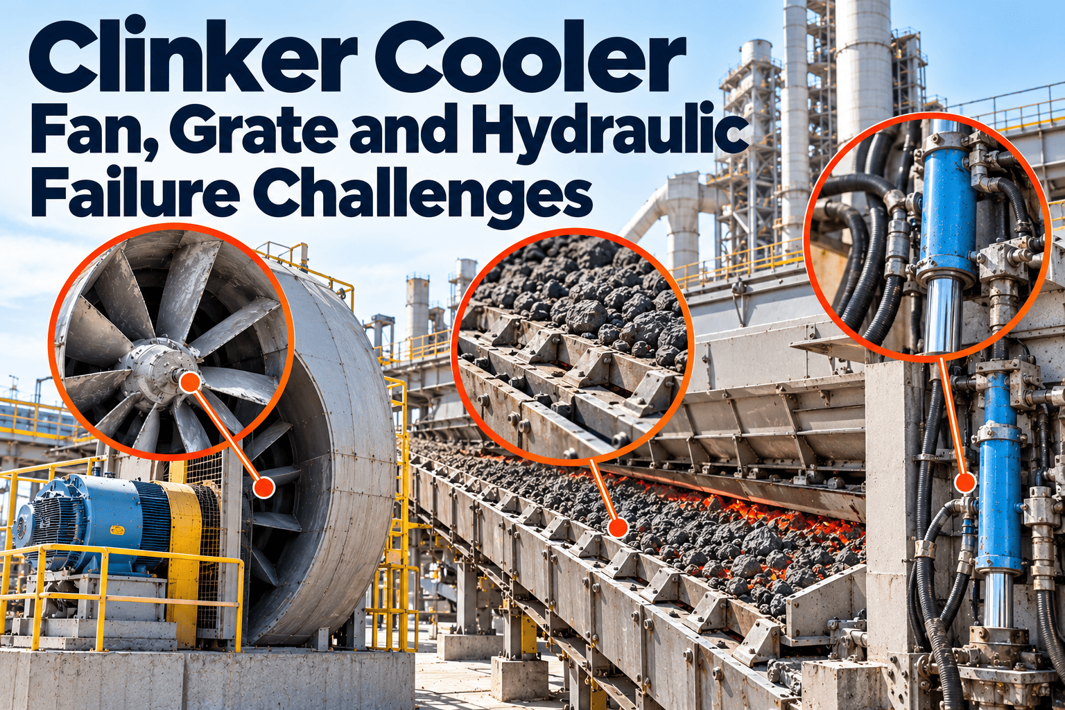
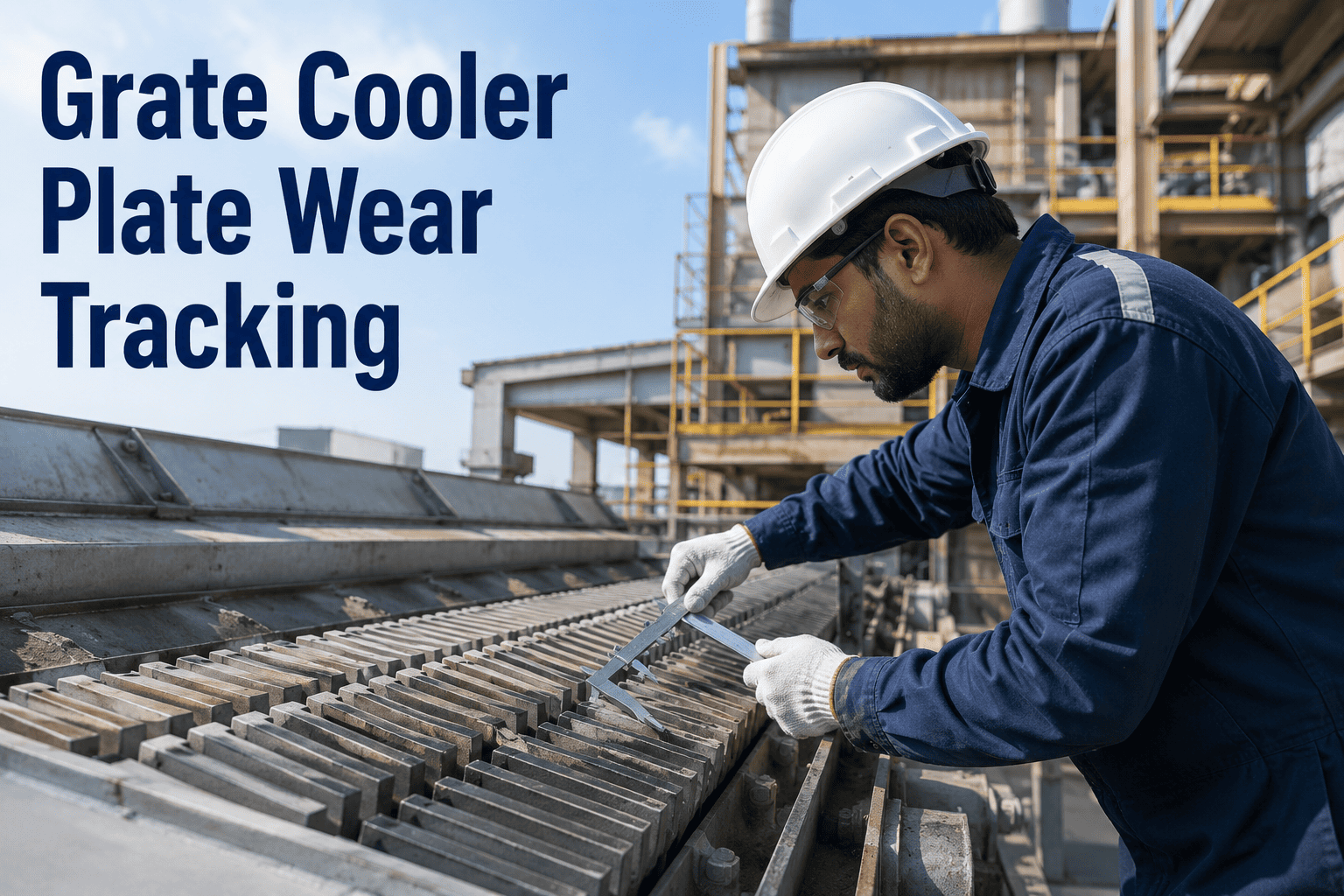
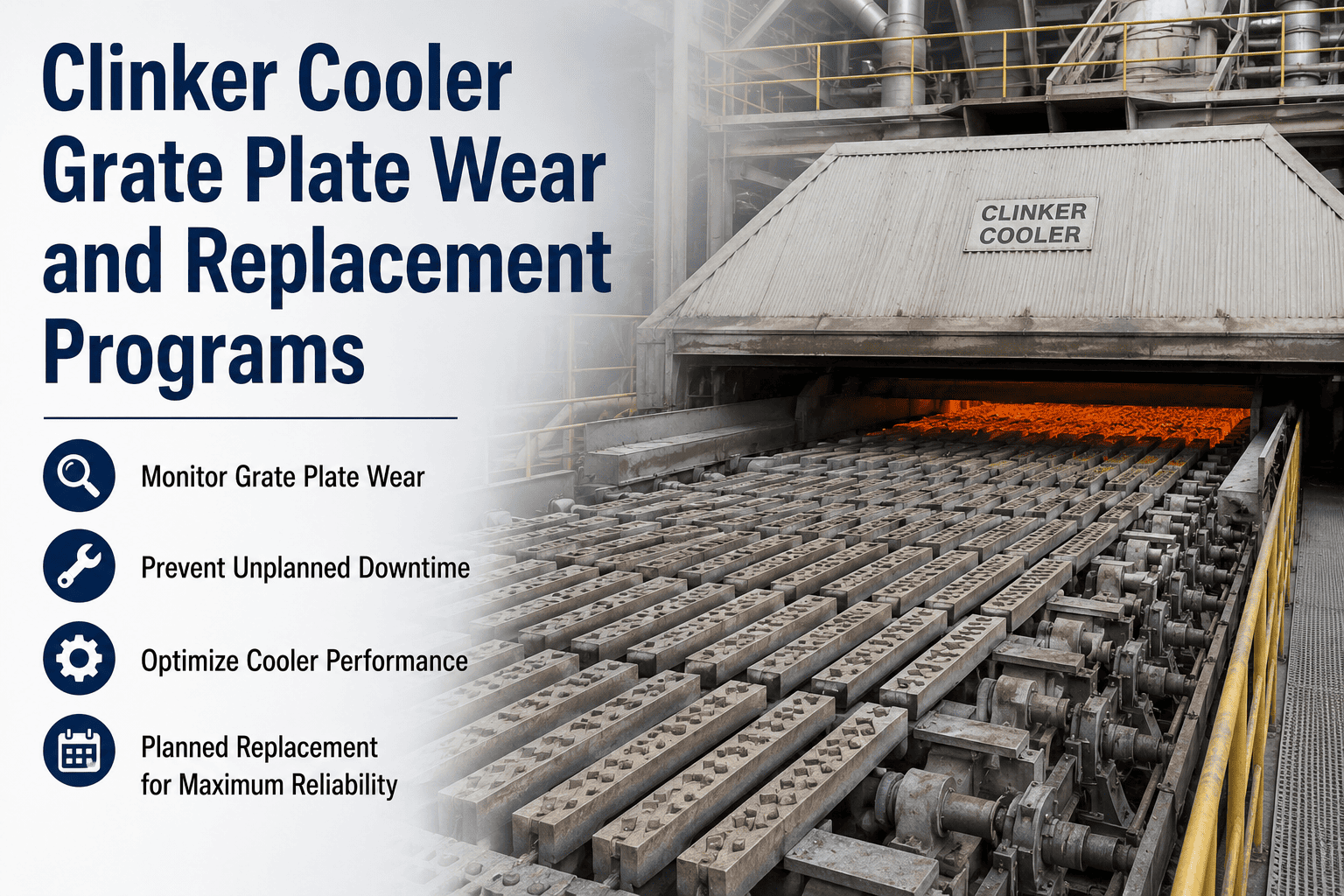
Zone 1 plates endure thermal cycling from ambient to 1,400°C and direct abrasion from clinker at over 1,000°C. Worn slots enlarge — clinker fines fall through, undergrate fans lose back-pressure, and hot air escapes downward instead of up through the bed. One cracked plate row can shift airflow distribution across the entire zone.
Signal: Red grate visible through inspection window, clinker fines on undergrate floor, fan amps rising on adjacent compartment fans.
Hot Air Loss — Secondary & Tertiary
Secondary air returns to the kiln at 1,050°C for combustion. Tertiary air drives the calciner. If the cooler is leaking — through worn expansion joints, hood gaps, or misaligned seals — hot air exits to atmosphere instead of the kiln. Every percentage point of loss raises specific heat consumption and increases fuel cost per tonne.
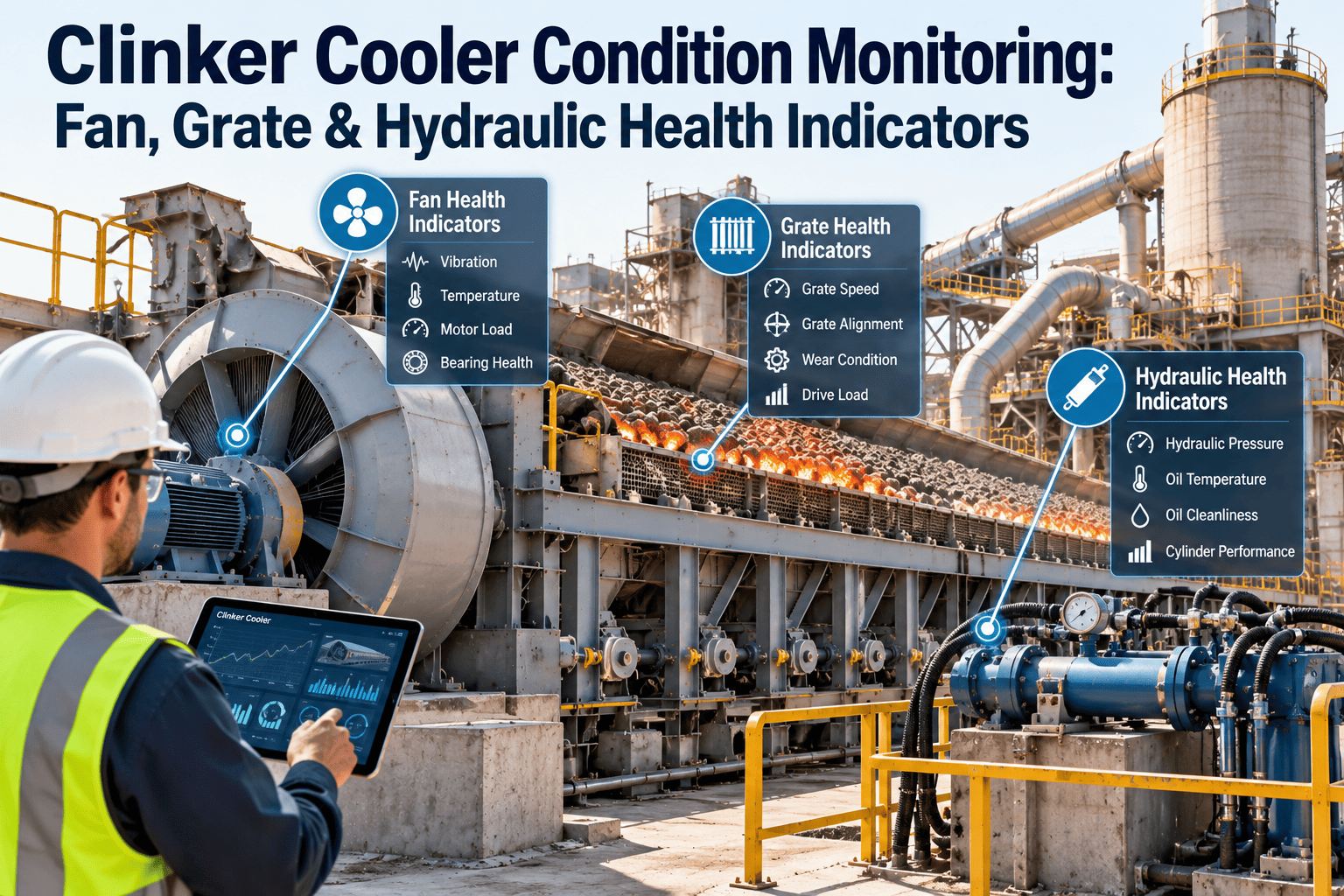
Undergrate fan amps rise when bed resistance increases — either from clinker buildup, a blocked grate section, or a fan bearing beginning to drag. Falling amps can indicate a blown impeller blade or duct blockage. Both are detectable a full shift before the fan trips — but only if daily amp readings are logged and compared to baseline.
Signal: Any fan running more than 10% above or below baseline amp draw for the current grate speed and bed depth.
Hydraulic Drive Health
The grate hydraulic drive moves the entire cooler reciprocation cycle. Hydraulic pressure spikes indicate excess clinker bed resistance — often from a snowman formation or clinker buildup at the inlet. Drive motor amperage rising with normal grate speed is an early warning of mechanical resistance before a full drive stall causes unplanned kiln stop.
Signal: Hydraulic pressure above setpoint at normal stroke speed, drive motor amps rising over 48-hour trend.
Red River and Channeling
Red river is a stream of overheated, partially fluid clinker that flows along the cooler side wall instead of distributing across the grate bed. It concentrates thermal load on one side, accelerates lateral wear plate erosion, and reduces average heat recovery because air channels through the low-resistance flow path rather than through the full bed depth.
Signal: Visual orange/red streak through inspection windows at cooler mid-section, asymmetric secondary air temp across cooler width.
Clinker Discharge Temperature
Target at cooler outlet is 65°C above ambient. Discharge temperature above 120°C means the bed is moving too fast, air distribution is insufficient, or grate plate wear has reduced airflow through a section. High discharge temperature also means cement grindability suffers — harder clinker increases mill power consumption and reduces mill throughput directly.
Signal: Thermocouple at cooler outlet reading above 120°C for more than one full shift without process justification.
OxMaint Logs Every Daily Cooler Reading — And Turns Threshold Breaches Into Work Orders Automatically
Fan amp baselines, undergrate pressure thresholds, grate plate wear records, and shift sign-off — all pre-configured for cement plant cooler operations in under 2 weeks.
Complete this walk at the start of each shift before reviewing DCS trends. Physical observation catches what the control room cannot — cracked plates, side-wall hot spots, and unusual clinker distribution patterns.
Zone 1 — Hot End Grate Inspection (Priority: Every Shift)
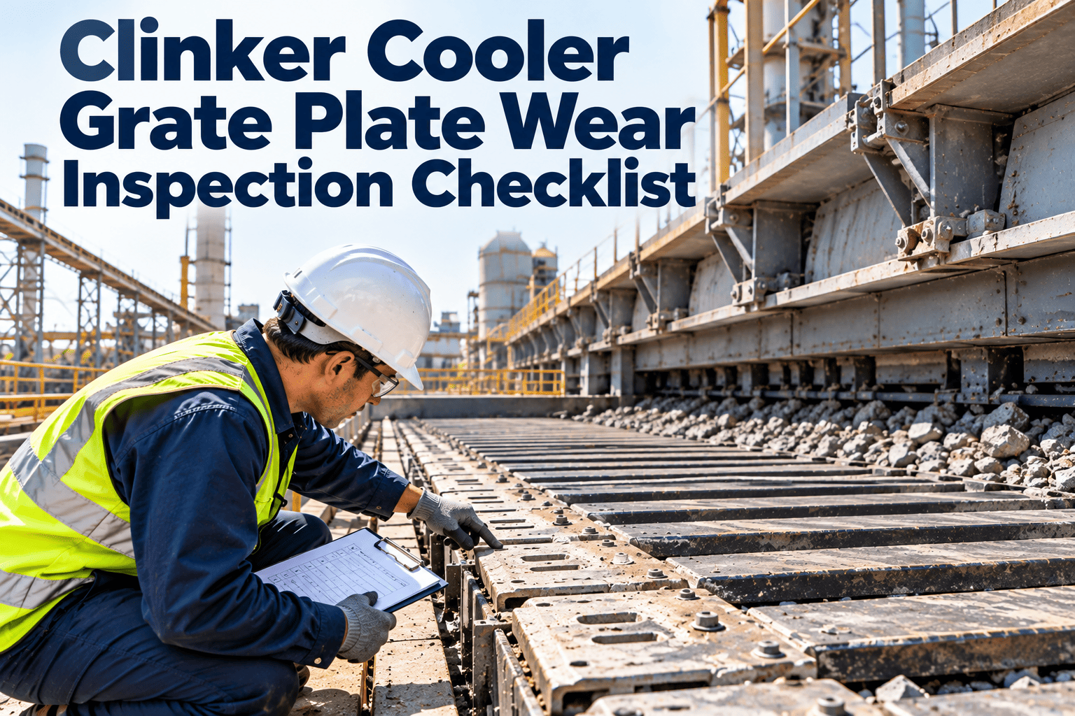
Inspect all Zone 1 grate plates through available inspection windows — look for visible cracks, broken slot edges, or deformed plate profile; any cracked plate is flagged for replacement at next planned stop
Tool: Inspection window + torch if needed · Log finding: good / crack visible / plate missing section
Check for clinker fines accumulation on undergrate floor below Zone 1 — fines falling through indicate worn slot openings; accumulation blocking fans is a fire and airflow risk
Action if fines visible: increase inspection frequency, flag for thickness measurement at next shutdown
Observe clinker bed depth at inlet — target 800mm in hot zone; shallow bed (below 600mm) allows air channeling and under-cools the grate; deep bed (above 1,000mm) causes grate overload and drive pressure spikes
Log bed depth estimate: shallow / target range / deep · Flag any shift outside target range
Check Zone 1 lateral wear plates at both side walls — hot fine clinker flowing along the side frame erodes lateral plates faster than grate plates; deformation visible as gap between plate edge and side frame
Log condition: good / gap forming / plate displaced · Flag if gap exceeds 20mm
Look for red-river formation — orange/red clinker streak along either side wall indicates maldistribution; report to CCR immediately if visible as it worsens heat recovery and accelerates side plate erosion
Immediate report to CCR: adjust grate speed and bed depth distribution; log event with estimated width and location
Zone 2 — Heat Recovery Zone Inspection (Priority: Every Shift)
Inspect grate plate condition in Zone 2 through available windows — plates here wear more slowly than Zone 1 but cracks accelerate during high-alkali clinker campaigns; note any visible deformation
Log condition per row inspected: good / crack / deformation observed
Check cooler hood and expansion joints for visible gaps, red-hot spots, or dust leaks — hot air leaking at Zone 2 hood reduces tertiary duct temperature and waste heat recovery turbine output directly
Flag any visible gap or hot spot for gasket replacement at next shutdown — log location reference
Check cooler side-wall refractory through any accessible inspection points — spalled castable or visible steel shell behind refractory is a shutdown-level finding; report immediately
Shutdown-level finding: visible steel shell · Log refractory condition: good / spall / monitoring point marked
Zone 3 — Cold End and Discharge Inspection
Check grizzly bars at cooler discharge — inspect for skewed, missing, or broken bars; a missing grizzly bar allows oversized clinker boulder to pass to the discharge conveyor and potentially jam the clinker breaker
Log condition: all bars present and aligned / gap found / bar broken — immediate work order if bar missing
Observe clinker particle size at discharge — excessively large clinker boulders indicate insufficient cooling time (grate speed too fast) or incomplete burning; oversized clinker at outlet also indicates clinker breaker hammer wear
Log: normal / boulders present / particle size coarser than prior shift · Flag boulders for CCR adjustment
Check spillage conveyor under Zone 3 for excessive fines accumulation — spillage above normal rates signals grate plate wear in the cold end; accumulated spillage blocking the conveyor causes airflow restriction and undergrate fan overload
Log spillage rate: normal / elevated / conveyor accumulating · Elevated rate: flag for thickness measurement
Fan Amperage and Undergrate Pressure — Daily Log Readings
These are the four control room readings every shift operator must log against baseline before signing off. Deviations that go unlogged are deviations that become emergencies.
Undergrate Fan Amperage
Baseline: Per fan nameplate and current grate speed
Within 10% of baseline — Log and continue
10–20% above baseline — Inspect fan inlet and bed resistance; create advisory work order
Above 20% or sudden drop — Fan bearing or impeller fault; urgent work order before next shift
Undergrate Pressure (Per Compartment)
Setpoint: Minimum 15 in. H₂O at hot zone; per design curve at other zones
Within ±2 in. H₂O of setpoint — Log and continue
Falling trend across 2 consecutive shifts — Grate plate wear or bed depth issue; advisory work order
Sharp drop in one compartment — Grate plate breach or duct blockage; urgent investigation
Secondary Air Temperature
Target: 1,000–1,100°C returning to kiln; plant-specific baseline
Within 30°C of baseline — Log and continue
30–60°C below baseline — Hot air loss or bed depth issue; check hood seals and grate speed
More than 60°C below baseline — Major air loss event; CCR escalation and immediate inspection
Clinker Discharge Temperature
Target: 65°C above ambient at cooler outlet (typically under 120°C)
Below 120°C — Log and continue
120–150°C — Insufficient cooling; check grate speed and fan air volume
Above 150°C for more than one shift — Clinker quality and downstream belt risk; urgent work order
Hydraulic Drive and Grate Speed Readings — Daily Log
Record grate drive motor amperage against current grate speed setting — rising amps at unchanged speed indicates increasing bed resistance from clinker buildup, snowman, or grate drag
Log: motor amps / grate speed (strokes per min) / hydraulic pressure reading · Flag if amps up more than 15% on stable speed
Check hydraulic station oil temperature — normal operating range per OEM specification; overheating indicates cooling circuit failure or excessive drive load from high bed resistance
Log: hydraulic oil temp °C · Flag above OEM upper limit — check hydraulic cooling circuit
Verify hydraulic accumulator nitrogen charge pressure — log reading; low charge causes erratic stroke behaviour and increases mechanical stress on the drive cylinder and connecting rods
Log: accumulator pressure bar / OEM minimum · Flag if below minimum — recharge before next shift
Check for any abnormal noise from grate drive mechanism during stroke cycle — clicking, grinding, or metallic impacts are early signs of roller and rail wear or loose grate frame support components
Log: no abnormal noise / noise type and location · Flag any new noise for mechanical inspection within 24 hours
Hot Air Loss Indicators — What to Check Every Shift
No visible gap, refractory intact at access points
Any flange gap, spalled refractory pieces visible in duct
Tertiary Air Duct Damper
Damper position matches DCS signal; no bypass gap at closed seat
Actual position within 5% of DCS set position
Position discrepancy greater than 5% or visible air bypass
Clinker Breaker, Grizzly, and Discharge — Daily Checks
Clinker Breaker (Hammer Mill)
Observe clinker particle size at breaker discharge — coarser output than prior shift indicates hammer wear; oversized boulders passing through indicate hammer-to-grate clearance has increased beyond spec
Listen for irregular impact sounds — metallic clang or uneven rhythm indicates a broken hammer or unbalanced rotor; log any change vs prior shift and flag for immediate inspection
Log breaker motor amperage — rising amps at normal throughput indicates hammer wear or boulder frequency increasing; sharp drop indicates material bypass or rotor stall condition
Grizzly Bars and Discharge Chute
Confirm all grizzly bars are present, aligned, and seated correctly — a missing bar allows boulders to pass directly to the discharge conveyor belt, causing belt damage and downstream conveyor jams
Check discharge chute for clinker buildup at bends — accumulated clinker at elbow transitions reduces throughput and generates impact loads that accelerate chute liner wear
Verify airlock valve operation at cooler discharge — sticking or non-seating airlock allows cold infiltration air upward into the cooler, reducing undergrate pressure and disrupting heat recovery in Zone 3
Shift Sign-Off and CMMS Record — Daily Cooler Log Fields
Every shift must produce a completed log entry in CMMS before handover. These are the six sign-off fields that constitute a valid daily cooler record for trend analysis and audit compliance.
1
Grate Walk Observation Record
Zone-by-zone observation result: good / crack visible / plate missing / red river / fines on undergrate floor. Location reference (row and zone) for any finding. Photograph if any defect observed.
2
Fan Amperage Log — All Active Fans
Actual amp reading vs baseline for every undergrate fan. Percentage deviation calculated. Any fan above threshold: advisory or urgent work order number recorded alongside the reading.
3
Undergrate Pressure and Secondary Air Temp
Per-compartment undergrate pressure reading. Secondary air temperature. Tertiary duct temperature if WHR system active. Any reading outside threshold range: deviation noted with timestamp.
4
Clinker Discharge Temperature
Thermocouple reading at cooler outlet. Grate speed at time of reading. Any adjustment made to grate speed or fan volume during shift to manage discharge temperature.
5
Hot Air Loss Check — Visual Findings
Hood seal, expansion joints, inspection doors: pass / flag. Location of any observed gap or dust emission. Estimated impact on secondary air temperature if major loss point found.
6
Shift Operator Sign-Off
Operator name and timestamp. All readings logged. Open work orders created for any threshold breach. Items deferred to next shift noted with reason. Maintenance lead notified of any urgent findings.
Frequently Asked Questions
How often should a grate plate walk be done on a cement plant clinker cooler?
Zone 1 (hot end) requires a visual inspection every shift — the combination of 1,100°C inlet temperature and continuous abrasion means plate condition can deteriorate from hairline crack to structural failure within 24–48 hours. Zone 2 and Zone 3 can be inspected once per day as a minimum. Any shift where fan amps or undergrate pressure deviates from baseline triggers a targeted Zone 1 inspection regardless of schedule. Set up shift-level cooler inspection schedules in OxMaint free — the checklist auto-assigns based on zone and shift rotation.
What does a rise in undergrate fan amperage mean during normal operation?
Rising fan amps at unchanged grate speed indicate increasing resistance against the fan — either from clinker buildup in the undergrate compartment, a grate plate breach reducing back-pressure, or early bearing drag in the fan itself. A 10% rise that holds across two consecutive readings warrants an advisory work order. A sudden 20%+ rise or a sudden drop is an urgent signal — blade damage or bearing failure. Logging fan amps every shift and comparing against a stored baseline is the only way to catch gradual drift before it becomes a fan trip. Book a demo to see fan amp trending configured in OxMaint for your cooler.
What causes hot air loss in a clinker cooler and how is it detected during daily operations?
The primary causes are worn or unseated cooler-to-kiln hood seals, cracked expansion joint fabric between cooler sections, and inspection door gaskets not fully latched. On the daily walk, look for visible heat plumes, dust emission at joint lines, or discolouration on steel around any seal. The control room signal is a falling secondary air temperature at unchanged clinker throughput — a drop of more than 30°C from baseline with no process reason should immediately trigger a physical check of all seal points. Start logging secondary air temp deviations in OxMaint to trend loss events across campaigns.
How can CMMS software improve daily clinker cooler management?
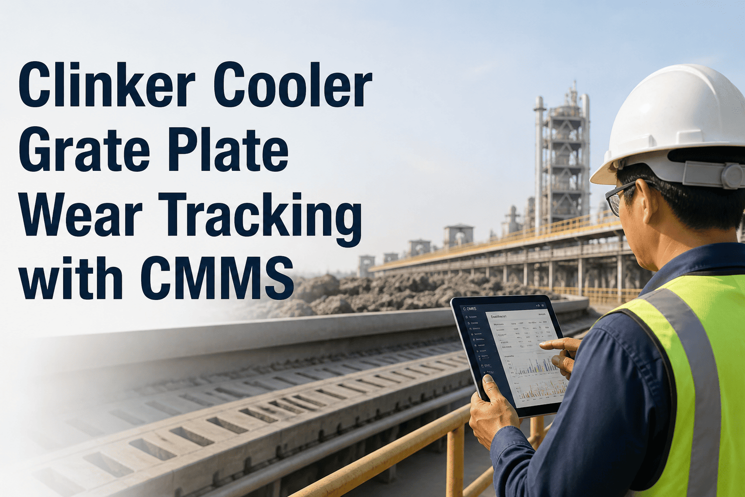
A properly configured CMMS removes the two biggest daily management failures: readings not logged and threshold breaches not actioned. OxMaint pre-configures baseline fan amp values, undergrate pressure setpoints, and secondary air temperature thresholds per zone. When a reading breaches a threshold, a work order generates automatically — not a dashboard alert that gets ignored, but an assigned work order with the asset, location, and required action pre-filled. Shift sign-off requires all readings to be entered before the handover can be closed. Book a demo to see the cooler daily log configured for your plant.
What is the correct clinker discharge temperature target and what does a high reading indicate?
Target is 65°C above ambient at the cooler outlet — typically below 120°C. A sustained reading above 120°C means the clinker is leaving with too much residual heat, which reduces cement grindability (harder clinker increases mill power consumption and reduces throughput), risks downstream conveyor belt damage, and indicates either insufficient air volume, excessive grate speed, or grate plate wear reducing airflow in the cold end zone. Adjusting grate speed or Zone 3 fan volume is the immediate response; a CMMS work order should be logged to trend the discharge temperature against grate plate condition records. Start free in OxMaint to link discharge temperature readings to Zone 3 grate condition records automatically.
Replace the Paper Cooler Log With a Live Daily Checklist — Configured in 2 Weeks
OxMaint pre-configures fan amp baselines, undergrate pressure thresholds, zone-level grate inspection schedules, secondary air temperature alerts, and shift sign-off workflows for your clinker cooler — no IT project, no spreadsheets, no missed readings.