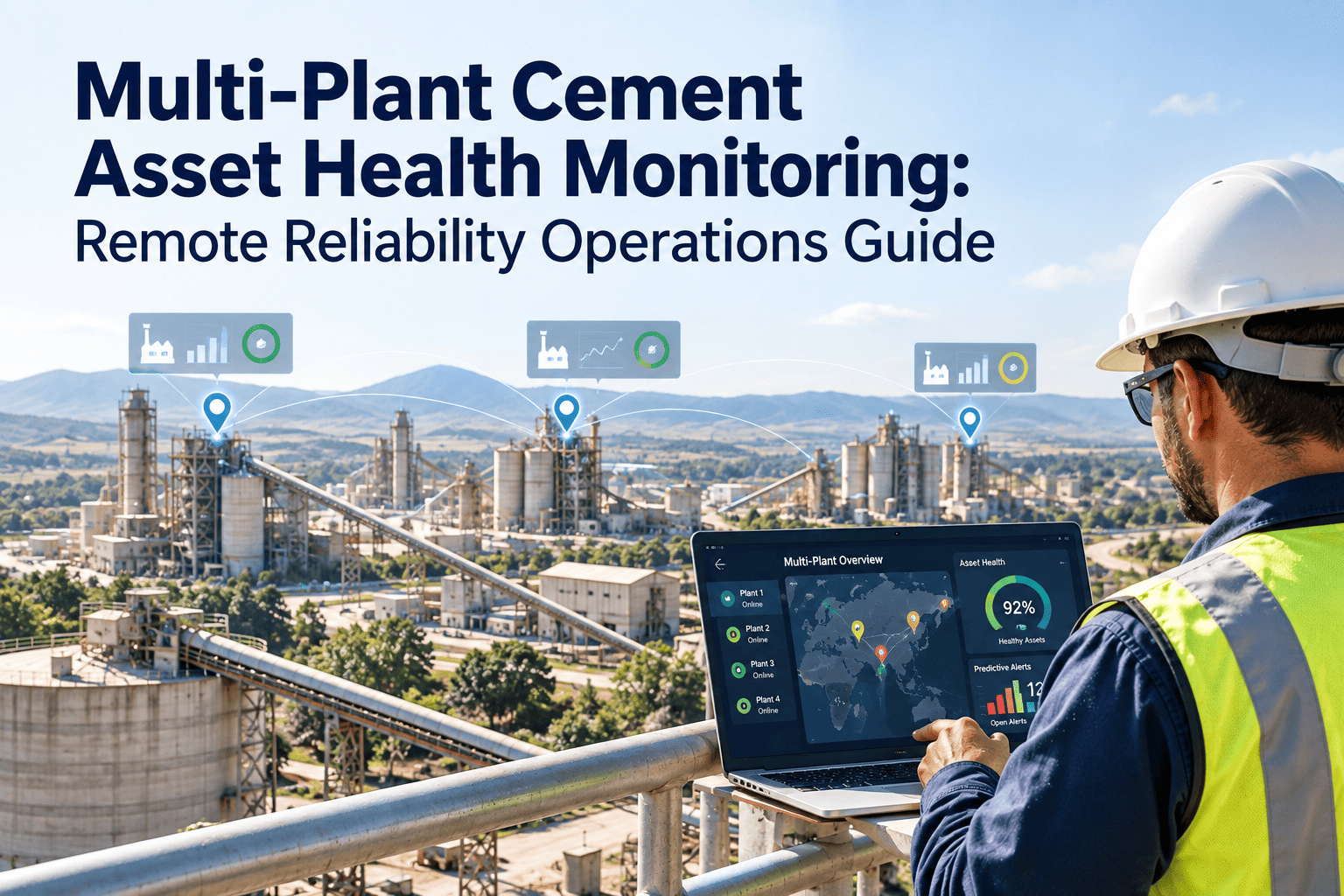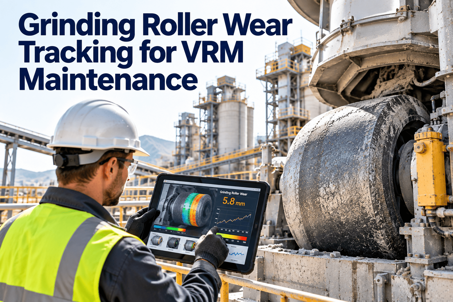
Vertical roller mills grind raw meal, coal, cement, and slag with a few heavy rollers pressed onto a rotating table, so roller condition sets throughput, specific power, and vibration stability. Wear is expected, but changing a roller set too early throws away expensive wear metal, while running it too long damages the table, hydraulics, and mill availability. This guide explains how cement plants can measure, trend, and forecast roller wear instead of relying on a fixed calendar. It also shows how Oxmaint maintenance software keeps the readings, work orders, and spares behind that decision in one record.
Grinding Roller Wear Tracking for VRM Maintenance
Replace rollers on measured wear, not on habit. Track profile loss, wear rate, and process signals so every overlay, turn, or change-out is planned with evidence.
The wear problem: two expensive mistakes
Most plants lose money on VRM rollers in one of two ways. Both come from not knowing how much usable wear metal is actually left.
Replacing too early
- Rollers are changed at a calendar interval or a fixed running-hour count
- Usable wear metal is scrapped, so cost per tonne ground rises
- Planned stoppages arrive more often than the material requires
- Spare sets and overlay budgets are consumed faster than needed
Replacing too late
- Worn profiles reduce grinding efficiency and raise kWh per tonne
- Vibration rises and the mill trips or runs at reduced feed
- Wear reaches the base metal, making repair or reuse impossible
- Failure forces an unplanned stop with no spare or crew ready
Where wear happens inside a VRM
Roller tyres get the attention, yet wear is spread across the whole grinding zone. Track each wear part separately because each one fails differently.
| Wear part | Typical wear pattern | What it does to the mill | What to record |
|---|---|---|---|
| Roller tyre or segments | Profile flattening, groove formation, edge rounding | Reduced grinding pressure efficiency and unstable bed | Profile depth at fixed stations |
| Grinding table liners | Track groove, uneven radial wear | Changes roller to table contact and bed formation | Groove depth and liner thickness |
| Hardfacing overlay | Cracking, spalling, delamination | Sudden loss of wear layer and rough surface | Crack map, photos, overlay date and procedure |
| Dam ring | Height loss, edge erosion | Changes bed depth and material retention | Ring height and condition |
| Nozzle ring or louvre vanes | Erosion by abrasive gas stream | Alters air velocity and material rejection | Vane thickness and gap changes |
| Mill body liners and separator parts | Abrasion in the gas path | Leakage, pressure drop shift, and product quality drift | Thickness readings and visual notes |
What drives roller wear rate
Wear rate is not constant between campaigns. Record the drivers beside each measurement so you can explain why one set lasted longer than another.
Measurement methods compared
The best method is the one your crew will repeat consistently at the same stations. Consistency matters more than instrument sophistication.
| Method | Strength | Limitation | Best use |
|---|---|---|---|
| Profile template or gauge | Simple, fast, low cost | Operator technique affects the reading | Routine shutdown checks |
| Depth gauge at marked points | Repeatable when stations are fixed | Only samples a few locations | Trend of wear rate per station |
| Laser or 3D profile scanning | Captures the full profile and shape change | Needs equipment, access, and data handling | Planning overlay or replacement |
| Ultrasonic thickness | Estimates remaining wall or segment thickness | Surface condition and coupling affect results | Segmented rollers and liners |
| Photo and crack inspection | Documents spalling and cracks | Not a measurement of depth | Evidence and overlay review |
A seven-step wear tracking routine
Follow the same sequence at every inspection so readings from different crews and years can be compared.
- Define stationsMark measuring points across each roller and the table track
- Set a baselineRecord the new or freshly overlaid profile with date and hours
- Inspect on scheduleMeasure at planned stops, not only when a problem appears
- NormalizeExpress wear per running hour and per tonne ground
- ForecastEstimate remaining life to the allowable limit
- DecideContinue, overlay, reposition, or replace
- Close the loopLog the action and compare the result with the forecast
Turning readings into a remaining life estimate
A simple linear estimate is a useful first pass. Treat it as a planning aid, because wear often accelerates once the hard surface is breached.
Illustrative example only
- Allowable wear is 60 mm and measured wear is 42 mm after 6,000 hours
- Wear rate is 7 mm per 1,000 hours
- Remaining wear is 18 mm, so about 2,570 hours remain
- Plan the stop earlier, because the rate may climb near the limit
- Use your supplier's allowable wear limit, not the figure in this example.
- Compare wear per tonne ground when feed rate changes between periods.
Process signals that confirm what the gauge shows
Physical measurement is the proof. Process data tells you when to measure sooner.
Put roller wear history in one place
Schedule wear measurements, store readings by station, and trigger overlay or replacement work from the data your crew collects.
Calendar-based versus condition-based roller maintenance
The change is not new technology. It is a shift from guessing remaining life to measuring it.
Calendar-based
- Change-out date fixed by past experience
- Measurements kept on paper or in personal files
- Wear differences between campaigns unexplained
- Spare rollers ordered late or ordered too early
- Overlay quality not linked to roller life
Condition-based
- Decision based on measured wear and trend
- Readings stored by asset, station, and date
- Wear rate compared against material and settings
- Procurement timed from forecast remaining life
- Each overlay recorded with its result
Choosing the action: continue, overlay, reposition, or replace
Define the trigger for each action before the shutdown, so the decision is not made under time pressure.
Continue running
Wear rate is stable, profile is within limits, no cracks or spalling, and vibration is normal. Schedule the next measurement.Overlay or hardface
Base metal is sound, wear is within the repairable range, and the supplier and procedure allow in-situ or workshop repair.Reposition or turn
Wear is uneven and the design permits turning or swapping so the worn side is rotated away from the grinding track.Replace
Wear has reached the limit, cracks threaten segment loss, or repair cost approaches replacement cost.Inspection checklist by interval
Adjust intervals to mill duty, material abrasiveness, and your wear parts supplier's guidance.
Daily and weekly
- Review vibration, power, and differential pressure trends
- Check hydraulic pressure and accumulator readings
- Inspect tramp metal separation equipment
- Note abnormal noise or product quality drift
Monthly or at short stops
- Check accessible wear parts for visible damage
- Inspect seals, grease points, and roller bearing temperatures
- Review spare availability against forecast
- Update the wear trend and remaining life estimate
Planned shutdown
- Measure all stations on rollers and the table track
- Photograph cracks, spalling, and overlay condition
- Inspect dam ring, nozzle ring, and louvre vanes
- Record the decision and the work done
Planning shutdowns and spares around wear forecasts
A good forecast is only useful if parts, welders, and crane time are ready when the mill stops.
- Several months outConfirm remaining life, order long-lead rollers or segments, and book specialist services.
- Weeks outVerify consumables, welding procedures, lifting tools, and crew qualifications.
- ShutdownMeasure, repair or replace, and record every parameter on the work order.
- After restartWatch vibration and power trends and set the new baseline.
KPIs for roller wear management
Track a small set of measures that connect wear, cost, and availability.
How Oxmaint supports roller wear tracking
Oxmaint is maintenance management software. It stores and schedules the work, while your measurements and engineering judgment set the decisions.
Asset hierarchy
Register each mill, roller, table, and hydraulic system so history stays with the right asset.Inspection checklists
Technicians record wear readings, notes, and photos on mobile at each station.Preventive scheduling
Plan measurement rounds, hydraulic checks, and shutdown inspections on set intervals.Work orders
Raise overlay, reposition, or replacement jobs when readings cross your action limits.Spare parts inventory
Track rollers, segments, liners, and welding consumables against planned demand.Reports and dashboards
Review backlog, completion, and repeat failures to refine intervals and budgets.What to log for every overlay and change-out
Wear life cannot be compared between campaigns unless the repair itself is recorded. Capture these details on the work order.
| Record | Why it matters | Example entry |
|---|---|---|
| Material ground and blend | Abrasiveness changes wear rate between periods | Raw meal with higher quartz share, or slag with changed clinker ratio |
| Running hours and tonnage | Allows wear per hour and per tonne to be compared | Hours since baseline and tonnes ground in the same period |
| Hydraulic and grinding settings | Pressure strongly influences contact stress | Nip pressure range used during the campaign |
| Overlay consumable and procedure | Shows which product and method last longest | Wire or electrode type, preheat step, number of layers |
| Welder and inspection result | Links quality to repair outcome | Crew name, visual check, and any crack repair |
| Failure or removal reason | Separates normal wear from damage | Reached limit, spalling, tramp metal, crack, or bearing issue |
Common mistakes in roller wear programs
These errors turn good measurement into misleading trends. Review them before building your inspection template.
Safe access and measurement practice
Wear measurement happens inside or next to heavy rotating equipment. Safety steps should be part of the inspection template, not an afterthought.
- Confirm lockout, isolation, and hydraulic pressure release before any entry, following site procedures.
- Allow the mill to cool and ventilate the interior, and check for residual material and dust before work.
- Secure rollers against movement and confirm that lifting and support arrangements are in place.
- Record the permit number on the same work order that holds the wear readings.
- Use the same trained inspectors where possible, so measuring technique stays consistent.
- Photograph the surface with a scale reference so later reviewers can see crack growth and spalling.
Grinding roller wear tracking FAQs
How often should VRM roller wear be measured?
Measure at every planned stop and more often as wear approaches the limit. Set the interval from mill duty and supplier guidance.
What causes premature roller replacement?
Fixed change-out dates, missing wear data, and unclear limits lead to early scrapping. Oxmaint keeps wear history beside each roller.
Can a CMMS predict roller life?
It stores trends and triggers work, while the estimate comes from your measured wear rate and engineering review.
Is hardfacing always better than replacement?
Not always. It depends on base metal condition, repair quality, and cost against replacement. Record results to compare.
Where should a plant start?
Fix measuring stations and a baseline, then schedule the rounds. Book a demo to plan the setup.
Know your roller life before the mill tells you
Give maintenance, process, and procurement one shared wear record, so every overlay and change-out is timed by evidence.